Form 4 Lighting Input Sheet
In the “Form 4 (Lighting) Lighting” input sheet, based on the electrical equipment drawings (such as lighting fixture list, floor plan, and lighting control diagram) describing the specifications of the lighting equipment, information shall be entered on the rooms where the lighting equipment is installed and the specifications of the lighting fixtures (fixture model/name, rated power consumption, and number of fixtures) as well as the lighting control method.
Format of Lighting Input Sheet
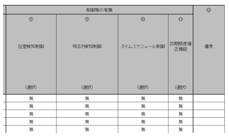
The format of the “Form 4 (Lighting) Lighting” input sheet is shown in Figure 4-1-1.
- ... (continued below)
Input Items and Input Method of the Lighting Input Sheet
The input items and input method of the “Form 4 (Lighting) Lighting” input sheet are shown below. The numbers in brackets preceding each item name correspond to the numbers in brackets shown at the top of Figure 4-1-1.
(1) Floor, Room Name, Building Use, Room Use, Room Area, Floor-to-floor Height, Ceiling Height
- Transcribe the floor, room name, etc., of the rooms subject to lighting calculation from among the rooms entered in Figure 1-2-1 Format of “Form 1 (Common Conditions) Room Specification” input sheet. Since full-width and half-width characters are distinguished, care shall be taken when entering data.
- These items must be identical in every respect - including uppercase and lowercase letters and spaces - to information in Figure 1-2-1 Format of “Form 1 (Common Conditions) Room Specification” input sheet. However, the order of rooms may differ.
- When two or more types of lighting fixtures are installed in the same room, or when the types of introduced control vary partially, list the specifications and types of control of the lighting fixtures side by side, and enter the floor, room name, etc., only for the topmost fixture, leaving these fields blank for the other fixtures.
- When evaluating lighting equipment installed under eaves, enter the horizontal projection area of the eaves as the room area.
(2)(3) Room Width and Room Depth
- Enter only when performing correction by room index. The unit is m.
- It is acceptable to leave (2)(3) blank and enter only (4) Room Index.
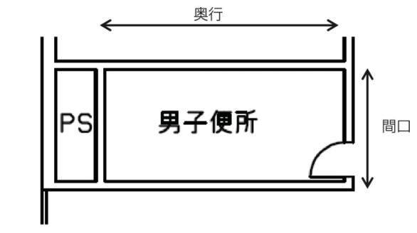
- When the room shape is rectangular, the width of the room facing the window shall be taken as the room width, and the distance from the window as the room depth (see Figure 4-1-2).
- Note that although “Room Width × Room Depth ≈ Room Area,” it does not have to match the room area exactly.
(4) Room Index
- Enter only when performing correction by room index.
- If room width and depth are entered in (2)(3), this field may be left blank. Enter a value in (4) only when specifying the room index directly.
- The room index shall be calculated by the following formula and entered as a numerical value (truncate at the fourth decimal place, and enter up to the third decimal place). The height of the working plane may be appropriately set according to the room use. Note that if room width and depth are entered in (2)(3), the Energy Consumption Performance Calculation Program (Non-Residential Version) automatically calculates the room index, in which case the working plane height is uniformly set to 0 m regardless of the room use.
- a) When the room is rectangular:
Room Index = Room Area / (Room Width + Room Depth) × (Ceiling Height − Working Plane Height)
- b) When the room is not rectangular:
Room Index = Room Area / (Room Perimeter ÷ 2) × (Ceiling Height − Working Plane Height)
(5) Name of Equipment
- Enter in text the symbol listed in the lighting fixture list of the design drawings, the name of lighting fixtures for public facilities, or the model number of the lighting fixture manufacturer, etc.
- Although not used for calculation, this information is necessary for cross-checking with drawings during review and shall always be entered.
(6) Rated Power Consumption
- Enter numerically the power consumption per each lighting fixture (input value including ballast). The unit is W/device.
- The power consumption of lighting fixtures shall, in principle, be the value measured in accordance with the method specified in JIS C 8105-3 “Luminaires — Part 3: General requirements for performance.”
- For fluorescent-lamp fixtures, HID fixtures, incandescent-lamp fixtures, and LEDs, the values listed in the guide published by Japan Lighting Manufacturers Association (JLMA), “Guide 114-2012: Representative Values of Electric Power Consumption of Luminaires for Calculating Coefficient of Energy Consumption for Lighting” may be used.
(7) Number of Devices
- Enter numerically the number of installed lighting fixtures.
(8) Presence or Absence of Control, etc. (Occupancy Detection Control)
- When occupancy detection control is adopted, select the control method from the options in Table 4-1-1 “Occupancy Detection Control” and enter its name as a string. If control is not adopted, enter “Absent.”
- “Occupancy Detection Control” refers to an automatic control system having the following function.
An automatic control system that detects human presence or absence by means of detection devices such as occupancy sensors, and automatically turns on the light when the room is occupied and turns it off or dims it by dimming control when unoccupied. Local flashing and/or dimming by manual switches is not subject to this item. In addition, occupancy detection control using cards or room keys is not subject to this item, as it is used for entry/exit management and does not contribute to energy-saving effects during working hours.
| Option | Application | Coefficient |
|---|---|---|
| Lower-limit dimming method | Method in which lighting is automatically dimmed to the lower limit or switched on/off based on signals from a continuous-dimming type occupancy sensor | 0.95 |
| On/off method | A method falling under any of the following:・Automatic on/off switching by energizing/de-energizing the circuit with an infrared automatic switch・Automatic on/off switching based on control signals from an on/off type occupancy sensor・Automatic on/off switching based on control signals from an on/off type occupancy sensor built into the luminaire | 0.70 |
| Step-dimming method | A method falling under any of the following:・Automatic step-dimming based on control signals from a step-dimming type occupancy sensor・Automatic step-dimming based on control signals from a step-dimming type occupancy sensor built into the luminaire | 0.80 |
| No | Other than the above. | 1.00 |
(9) Presence or Absence of Control, etc. (Illuminance Detection Control)
- When illuminance detection control is adopted, select from the options in Table 4-1-2 “Illuminance Detection Control”, and enter the control name as a character string. If no control is adopted, enter “Absent.”
- “Illuminance Detection Control” refers to an automatic control system having the following functions.
An automatic control system that detects variations in indoor illuminance through sensors or other detection devices and adjusts the lighting output so that the room maintains the preset illuminance. Local flashing and/or dimming by manual switches is not subject to this item.
When selecting “Dimming System W15,” “Dimming System W20,” or “Dimming System W25,” it is necessary to indicate the calculation basis for the aperture ratio.
When selecting “Dimming System W15BL,” “Dimming System W20BL,” or “Dimming System W25BL,” it is necessary to clearly state in the design documents that the requirements for automatic-control blinds are satisfied, and to indicate the calculation basis for the aperture ratio and for the installation ratio of automatic-control blinds.
| Option | Application | Coefficient |
|---|---|---|
| Dimming method | Method in which lighting is automatically dimmed based on control signals from a continuous-dimming type daylight sensor | 0.90 |
| Dimming method BL | Method in which lighting is automatically dimmed based on control signals from a continuous-dimming type daylight sensor, combined with automatically controlled blinds | 0.85 |
| Dimming method W15 | Method in which lighting is automatically dimmed based on control signals from a continuous-dimming type daylight sensor・The opening ratio must be 15% or more. | 0.85 |
| Dimming method W15BL | Method in which lighting is automatically dimmed based on control signals from a continuous-dimming type daylight sensor, combined with automatically controlled blinds・The opening ratio must be 15% or more.・The coverage ratio of the automatically controlled blinds must be 50% or more. | 0.78 |
| Dimming method W20 | Method in which lighting is automatically dimmed based on control signals from a continuous-dimming type daylight sensor・The opening ratio must be 20% or more. | 0.80 |
| Dimming method W20BL | Method in which lighting is automatically dimmed based on control signals from a continuous-dimming type daylight sensor, combined with automatically controlled blinds・The opening ratio must be 20% or more.・The coverage ratio of the automatically controlled blinds must be 50% or more. | 0.70 |
| Dimming method W25 | Method in which lighting is automatically dimmed based on control signals from a continuous-dimming type daylight sensor・The opening ratio must be 25% or more. | 0.75 |
| Dimming method W25BL | Method in which lighting is automatically dimmed based on control signals from a continuous-dimming type daylight sensor, combined with automatically controlled blinds・The opening ratio must be 25% or more.・The coverage ratio of the automatically controlled blinds must be 50% or more. | 0.63 |
| On/off method | A method falling under any of the following:・Automatic on/off switching based on control signals from a continuous-dimming type daylight sensor・Automatic on/off switching by energizing/de-energizing the circuit based on brightness detection by an automatic light switch・Automatic on/off switching by energizing/de-energizing the circuit based on brightness detection by an infrared automatic switch (with daylight sensor) | 0.80 |
| No | Other than the above. | 1.00 |
- The formula for calculating the aperture ratio shall be as follows.
Aperture Ratio = (Total area of openings in the space subject to calculation [m²]) / (Floor area of the space subject to calculation [m²]) × 100
“Space subject to calculation” refers to one continuous space enclosed by exterior walls, interior walls, etc.
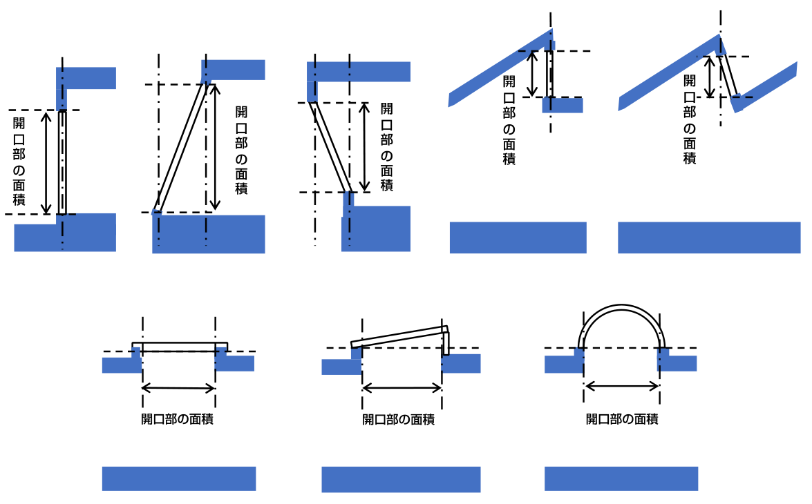
The area of openings (limited to those located on walls or roof surfaces that are either openable to the outdoors or made of light-transmitting materials) shall be determined in accordance with the calculation of the area of openings under the simple aperture ratio defined in the Japanese Housing Performance Labeling Standards, as shown below (Figure 4-1-3):
a. For openings located on walls or roof surfaces that are vertical openings, upward-facing openings inclined more than 0 degrees and not more than 45 degrees from the vertical, or downward-facing openings, their area shall be taken as the vertical projected area (including the sash portion).
b. For openings on roof surfaces that are upward-facing and inclined more than 45 degrees and not more than 90 degrees from the vertical, their area shall be taken as the horizontal projected area (including the sash portion).
As for devices that guide outdoor light into indoor spaces (daylight devices), since verification regarding their effect is insufficient at present, they shall be excluded from evaluation for the time being.
- “Automatic-control blind” refers to a system that automatically adjusts the slat angles of blinds to allow daylight into indoor spaces as much as possible in order to achieve a higher effect of reducing lighting energy consumption, while preventing glare in clear weather and maximizing daylight introduction in cloudy weather.
- Under the Energy Conservation Standard, only those satisfying the following requirements (a to f) shall be treated as “automatic-control blinds”:
a. They shall be horizontal blinds installed on openings facing outdoors, and the main body shall be equipped with an electric motor.
b. They shall have a function for adjusting the slat (blade) angle in steps of 10 degrees or less, or with 18 steps or more.
c. They shall have a function for calculating, at intervals of 10 minutes or less throughout the year, the protection angle of slats (the angle relative to the horizontal plane required to block direct sunlight) when direct sunlight strikes the blinds under clear weather, based on the building location (latitude and longitude), the orientation of the blinds, and the solar position (elevation and azimuth).
d. They shall have equipment for measuring any of outdoor illuminance, solar radiation, or luminance.
e. They shall have a function for determining clear or cloudy conditions, using any one of the calculated values of direct solar illuminance, normal-incidence direct solar radiation, or solar luminance, which are calculated from the measured values of outdoor illuminance, solar radiation, or luminance (clear when the calculated value exceeds the set threshold, and cloudy when it is below the threshold).
f. They shall have a function for transmitting the control signal corresponding to the slat angle determined by the clear/cloudy judgment to the electric motor attached to the blind body.
- Although automatic control of vertical blinds can be implemented by the same system as for horizontal blinds, they shall not be evaluated for the time being, because at present the dissemination rate of vertical blinds is significantly lower than that of horizontal blinds and the evidence regarding their energy-saving effect is insufficient.
- In the relevant room subject to lighting calculation, the ratio [%] of the total area of openings equipped with automatic-control blinds to the total area of openings shall be defined as the installation ratio of automatic-control blinds.
The “space subject to calculation” used in the calculation of the aperture ratio may differ from the “room” defined in “Form 1 Room Specifications Input Sheet.” It is because the “room” defined in “Form 1 Room Specifications Input Sheet” is determined taking into account not only lighting but also air-conditioning zoning, etc.
Example: If separate air conditioners are installed for the perimeter and the interior of one space, the space shall be divided into two and each treated as one room for input. In such a case, input for lighting fixtures (Form 4) must also be separately performed for the perimeter and for the interior. Although lighting fixture specifications, etc., are entered separately for perimeter and interior in Form 4, for the calculation of the above aperture ratio, the perimeter and interior shall be regarded as one space (that is, the aperture ratio will have the same value for both the interior and perimeter).
Input Example 1: When one space corresponds to one room in Form 1:
Aperture Ratio = 20 / 100 × 100 = 20%
Input Example 2: When one space corresponds to two rooms in the web program:
※ ※Here, it's assumed that different air conditioners are installed for the interior side and perimeter side (although there is no partition between them)
Aperture Ratio = 40 / (180 + 20) × 100 = 20% for both Room 1 and Room 2.
(10) Presence or Absence of Control, etc. (Time-Schedule Control)
- When time-schedule control is adopted, select from the options in Table 4-1-3 “Time-Schedule Control”, and enter the control name as a character string. If no control is adopted, enter “Absent.”
- “Illuminance Detection Control” refers to an automatic control system having the following functions.
An automatic control system that turns on/off or dims lighting at preset times set on a lighting control panel or the like. Local flashing and/or dimming by manual switches is not subject to this item.
| Option | Application | Coefficient |
|---|---|---|
| Step-dimming method | Method in which luminaires are dimmed according to preset times | 0.95 |
| On/off method | Method in which luminaires are switched on/off according to preset times | 0.90 |
| No | Other than the above. | 1.00 |
(11) Presence or Absence of Control, etc. (Initial Illuminance Correction Function)
- When initial illuminance correction is adopted, select the relevant specification from the options in Table 4-1-4 “Initial Illuminance Correction Function”. If it is not adopted, enter “Absent.”
- “Initial Illuminance Correction Control” refers to a function that starts lighting at a luminous flux obtained by multiplying the rated luminous flux by the maintenance factor and maintains an almost constant luminous flux over the maintenance period. The implementation of this function shall employ either (a) a built-in timer that records lighting time or (b) a dimming signal from an illuminance sensor or the like.
| Option | Application | Coefficient |
|---|---|---|
| Timer method (LED) | Method in which the luminous flux of LED luminaires is kept constant by a built-in timer | 0.95 |
| Timer method (fluorescent) | Method in which the luminous flux of fluorescent luminaires is kept constant by a built-in timer | 0.85 |
| Sensor method (LED) | Method in which the luminous flux of LED luminaires is kept constant using a brightness sensor | 0.95 |
| Sensor method (fluorescent) | Method in which the luminous flux of fluorescent luminaires is kept constant using a brightness sensor | 0.85 |
| No | Other than the above. | 1.00 |