Input of Air Conditioning Equipment
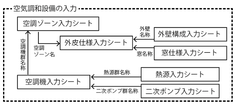
This chapter explains the evaluation method for air conditioning equipment. There are seven input sheets related to air conditioning equipment.
- In Form 2-1 “Air-Conditioned Zone Input Sheet”, information on the rooms subject to air conditioning calculation shall be entered. The “Name of Air Conditioner Group” entered in this sheet is defined in Form 2-7 “Air Conditioner Input Sheet.”
- Regarding the specifications of the building envelope, the thermal insulation specifications of the exterior wall shall be entered in Form 2-2 “Exterior Wall Configuration Input Sheet,” and the specifications of the windows shall be entered in Form 2-3 “Window Specifications Input Sheet.” Using these, Form 2-4 “Envelope Specifications Input Sheet” shall be prepared.
- The names of the air-conditioned zones entered in Form 2-4 “Envelope Specifications Input Sheet” are defined in Form 2-1 “Air-Conditioned Zone Input Sheet.”
- Regarding the specifications of equipment, the specifications of the heat source group shall be entered in Form 2-5 “Heat Source Input Sheet,” and the specifications of the secondary pump group shall be entered in Form 2-6 “Secondary Pump Input Sheet.” Using these, the specifications of the air conditioner group shall be entered in Form 2-7 “Air Conditioner Input Sheet.”
※Rules for Input of Envelope
[Method of Calculating the Area and the Height of Envelope]
- When calculating envelope area, use the wall centerline for the width of the exterior wall, and the floor-to-floor height for the height. If the floor-to-floor height differs depending on the location, the area shall be calculated according to the floor-to-floor height at each location.
The floor-to-floor height shall be measured from the top surface of the floor slab to the top surface of the floor slab on the upper floor. For simplification, it is acceptable to use the height between floor levels instead of between slab levels as the floor-to-floor height. For the floor-to-floor height of the lowest floor excluding the basement, it is acceptable to use the height from the ground surface (ground level) to the top surface of the floor slab of the upper floor.
The floor-to-floor height of the top floor shall be measured, for roof insulation, from the top surface of the floor slab of the top floor to the top surface of the roof slab, and for ceiling insulation, from the top surface of the floor slab of the top floor to the lower end of the ceiling insulation.
If the insulation material is in contact with ceiling finishes at the top floor, it is acceptable to calculate the floor-to-floor height at the lower end of the ceiling surface.
- The roof area shall be the area of the thermal boundary portion. In the case of sloped roofs with roof insulation, the roof area shall be the actual sloped area depending on the slope. In the case of ceiling insulation parallel to the sloped roof, the horizontal projection area of the relevant ceiling surface shall be used as the roof area.
- For flat roofs, because the difference caused by the drainage slope is minimal, the horizontal projection area shall be used as the roof area.
- The roof area shall include the floor area of rooftop equipment penthouses (as defined in Article 2, Paragraph 1, Item (viii) of the Enforcement Order of the Building Standards Act) that are not counted in the number of stories. If the insulation specifications of the area beneath the penthouse differ from those of the roof, for example in the case insulation is not installed on the area beneath the penthouse, the area shall be calculated separately for the roof and the area beneath the penthouse, and each shall be entered as a separate envelope.
[[Method of Calculating Thermal Transmittance]]
- When gypsum board or similar is being surface mounted on the ceiling (where the board does not extend to the horizontal structural members), the relevant gypsum board, etc., shall not be included in the calculation of thermal transmittance.
- For ceiling voids with roof insulation and/or ceiling insulation, one of the following three methods shall be applied for the time being. As a general rule, apply Method (1) for ceiling return systems, apply Method (3) if the ceiling void is not open to outdoor air and not a ceiling return system, and apply Method (2) if the ceiling void is open to outdoor air.
1) Enter only the roof insulation material. In this case, the height of the exterior wall shall be measured up to the roof insulation material.
2) Enter only the ceiling insulation material. In this case, the height of the exterior wall shall be measured up to the ceiling insulation material.
3) Treat the ceiling void space as a single layer composition and enter ceiling insulation material + ceiling void (non-airtight hollow layer) + roof insulation material. In this case, the height of the exterior wall shall be measured up to the ceiling insulation material.
[Treatment of Insulation Defects, etc.]
- For openings (such as sleeves) penetrating exterior walls that are continuously provided for equipment piping or small-diameter spiral ducts, relevant defect portions shall be regarded as having walls of the same insulation specification as the surrounding wall.
- For areas where there is no floor around the outlets for equipment piping, etc. (e.g., areas around equipment piping rising in rooftop penthouses), if the roof is flat type and insulated (except for roof of rooftop portions not counted as stories), the total area of the entire roof (including defect areas at equipment piping outlets) shall be entered, and the defect areas shall be regarded as having roof portions of the same insulation specifications as the roof. In this case, it is not necessary to enter the area of the rising wall of the equipment piping outlet as an envelope area.
For the calculation of thermal transmittance of columns, beams, etc., for the time being, the influence of insulation defects shall not be considered (Even if columns or beams are non-insulated, they shall be regarded as having the same insulation specifications as the surrounding insulated portions.).
[Treatment of Non-transparent Steel Building Fixtures, etc.]
- Among non-transparent steel building fixtures, etc., those whose dimensions and specifications, etc., are described in the List of Building Fixtures shall be treated as openings and entered in Form 2-3 (However, for the time being, it is acceptable to treat them as non-insulated walls according to the conventional input method and enter them in Form 2-2). Examples of such components include:
a) Doors (steel, resin, wood). These include fire doors, smoke control doors, wind pressure resistant doors, soundproof doors, and emergency doors.
b) Shutters (steel, resin, wood).
c) Louvers (OA louvers, SA louvers).
- For boards, etc., of spandrel portions of glass curtain walls, if their dimensions and specifications are described in the List of Building Fixtures, they shall, in principle, be treated as openings and entered in Form 2-3.