Form 3-3 Alternative Ventilation Air Conditioner Input Sheet
In the “Form 3-3 (Ventilation) Alternative Ventilation Air Conditioner” input sheet, enter information concerning the cooling capacity, rated output, etc., of the air conditioners installed to handle equipment heat load in place of mechanical ventilation equipment (hereinafter referred to as “alternative ventilation air conditioners”), based on the air-conditioning and ventilation equipment drawings (equipment list, system diagram, floor plan, automatic control diagram, etc.) that describe the specifications of mechanical ventilation equipment.
Format of the Alternative Ventilation Air Conditioner Input Sheet
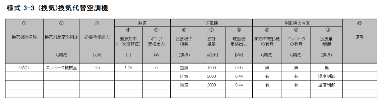
The format of “Form 3-3 (Ventilation) Alternative Ventilation Air Conditioner” input sheet is shown in Figure 3-3-1.
Input Items and Input Method of the Alternative Ventilation Air Conditioner Input Sheet
The input items and input methods of the “Form 3-3 (Ventilation) Alternative Ventilation Air Conditioner” input sheet are shown below. The numbers in brackets preceding each item name correspond to the numbers in brackets shown at the top of Figure 3-3-1.
(1) Name of Equipment
- Enter the name of the alternative ventilation air conditioner using a character string.
- The entered name must be identical to the ventilation equipment name entered in Figure 3-1-1 “Form 3-1 (Ventilation) ‘Room Subject to Ventilation Input Sheet.’”
(2) Room use of the room to be ventilated
- Select the room use of the room subject to ventilation from Table 3-3-1.
- This selection determines the average annual load factor of the room subject to ventilation.
| Option | Application |
|---|---|
| Electrical room | Electrical room or equivalent |
| Machine room | Machine room or equivalent |
| Elevator machine room | Elevator machine room or equivalent |
| Other | Other than the above |
(3) Required Cooling Capacity
- Enter the rated cooling capacity of the alternative ventilation air conditioner (or the required cooling capacity listed in the equipment list of the design drawings) as a numerical value. The unit is kW.
- If the capacity of the equipment to be installed is expected to have a capacity margin, the required capacity may be calculated and this value may be entered. For example, if there are installed two units in preparation for a failure and each unit has 100% of required cooling capacity, only the capacity for one unit may be entered. However, the basis for calculating this required capacity must be submitted separately.
(4) Heat Source Efficiency (converted primary energy value)
- For Heat Source Efficiency, enter, as a numerical value converted into primary energy, the heat source system efficiency (considering all energy consumption of the heat source main module, primary pump, heat storage-related pumps, cooling water pump, cooling tower, etc.).
- For packaged air conditioners, enter the value obtained by dividing the cooling capacity by the energy consumption of the outdoor unit (sum of the energy consumption of the compressor, heat exchange fan, etc.).
- For electric heat sources, enter the heat source efficiency (converted into primary energy) calculated from the rated cooling capacity and rated power consumption using the following equation.
Heat Source Efficiency = Rated Cooling Capacity [kW] / (Rated Power Consumption [kW] × 9760 / 3600)
(5) Pump Rated Output
- For central heat source-type systems, enter the rated output of the electric motor of the secondary chilled-water pump as a numerical value. The unit is kW.
- When the secondary chilled-water pump is shared with other air conditioners, enter only the portion of capacity corresponding to the relevant air conditioner (i.e., allocate the electric motor output of the secondary chilled-water pump in proportion to the cooling capacity of each air conditioner).
- When the alternative ventilation air conditioner is a packaged air conditioner, enter “0.”
(6) Type of Fan
- Select the applicable fan type from Table 3-3-2.
- When multiple fans are installed in the same alternative ventilation air conditioner, list items (6) through (11) sequentially, entering items (1) through (5) only for the uppermost equipment, and leaving the others blank.
| Option | Application |
|---|---|
| Air conditioning | Fan belonging to the alternative ventilation air conditioner and supplying cooling |
| Supply air | Fan installed in the same room as the alternative ventilation air conditioner and operating in conjunction with it, whose main role is air supply |
| Exhaust air | Fan installed in the same room as the alternative ventilation air conditioner and operating in conjunction with it, whose main role is air exhaust |
| Circulation | Fan installed in the same room as the alternative ventilation air conditioner and operating in conjunction with it, whose main role is air circulation |
(7) Design Airflow Rate
- Enter according to the same rules as item (2) “Design Airflow Rate” of Form 3-2 “Supply/Exhaust Air Fan Input Sheet.”
(8) Electric Motor Rated Output
- Enter according to the same rules as item (3) “Electric Motor Rated Output” of Form 3-2 “Supply/Exhaust Air Fan Input Sheet.”
(9)(10)(11) Presence or Absence of Control, etc.
- Enter according to the same rules as item (4), (5), and (6) of Form 3-2 “Supply/Exhaust Air Fan Input Sheet.”
Method for Calculating Required Cooling Capacity When a Spare Alternative Ventilation Air Conditioner Is Installed
For item (2) “Required Cooling Capacity” of the alternative ventilation air conditioner, it is acceptable to enter the total rated cooling capacity (or the required cooling capacity listed in the equipment list) of the equipment excluding the spare device, provided that the design drawings clearly indicate which devices are spare. The specific method for calculating the required cooling capacity is described below. However, if the calculation process and basis can be clearly presented, it is acceptable to use a required cooling capacity obtained by another method.
(1) From the total transformer capacity of all electric rooms in the entire building and the assumed contract power, determine the assumed average load factor for the entire building. First, calculate the assumed contract power using the following equation. According to “Building Mechanical and Electrical Engineer (December 2009 issue), Annual-Report of Building Mechanical and Electrical Equipment Information,” the average contract power per unit floor area is 0.0812 kW/m²; therefore, 0.082 kW/m² shall be used here.
Assumed Contract Power [kW] = Average Contract Power per Unit Floor Area [kW/m²] × Total Floor Area of the Target Building for Calculation [m²]
Next, calculate the assumed average load factor from the total transformer capacity of the auxiliary electric rooms and the assumed contract power using the following equation.
Assumed Average Load Factor [–] = Assumed Contract power [kW] / Total Transformer Capacity of Auxiliary Electric Rooms [kW]
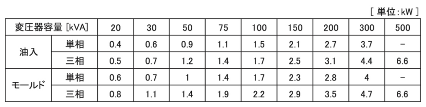
(2) Calculate the heat generation from the transformer capacity of the electric room subject to calculation. Determine the maximum heat generation of the electric room (heat generation when the load factor is 100%) based on “Building Equipment Design Standards (2015 Edition)”, supervised by Ministry of Land, Infrastructure, Transport and Tourism (MLIT), Minister's Secretariat, Government Buildings Department, Equipment and Environment Division, Part IV Air Conditioning Equipment, Chapter 4 Ventilation Equipment, Table 5-3 “Heat Generation H of Type 1 Transformers for Specific Equipment” (see Table 3-3-3).
(This table is provided in Japanese. An HTML version is planned for a future update.)
(3) From the heat generation of the electric room subject to calculation and the assumed average load factor for the entire building, calculate the required cooling capacity of the electric room using the following equation. The coefficient 0.15 in the equation represents the no-load loss rate.
Required Cooling Capacity = (Heat Generation of Electric Room × 0.15) + (Heat Generation of Electric Room × 0.85) × (Average Load Factor)²