Form 3-2 Supply/Exhaust Fan Input Sheet
In the “Form 3-2 (Ventilation) Supply/Exhaust Air Fan” input sheet, enter information regarding the rated airflow rate, rated output, control method, etc., of supply/exhaust air fans, based on the air-conditioning and ventilation equipment drawings (equipment list, system diagram, floor plan, automatic control diagram, etc.) that describe the specifications of ventilation equipment.
Format of the Supply/Exhaust Air Fan Input Sheet
The “Form 3-2 (Ventilation) Supply/Exhaust Air Fan” input sheet is shown in Figure 3-2-1.
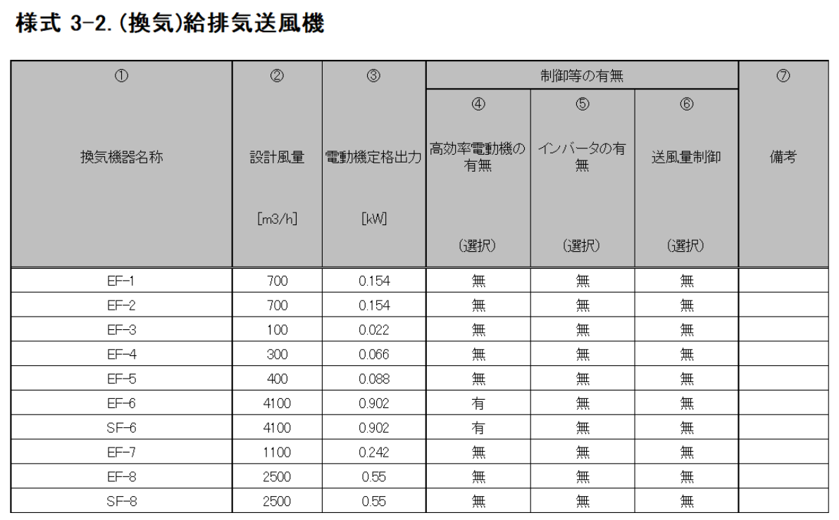
Input Items and Input Method of the Supply/Exhaust Air Fan Input Sheet
The input items and input methods of the “Form 3-2 (Ventilation) Supply/Exhaust Air Fan” input sheet are shown below. The numbers in brackets preceding each item name correspond to the numbers in brackets shown at the top of Figure 3-2-1.
(1) Name of Ventilation Equipment
- Enter the name of the ventilation equipment using a character string.
- The entered name must be identical to the ventilation equipment name entered in Figure 3-1-1 “Form 3-1 (Ventilation) Room Subject to Ventilation" input sheet.
(2) Design Airflow Rate
- Enter, in numerical form, the design airflow rate of the supply/exhaust air fan (or the rated airflow rate listed in the equipment list of the design drawings). The unit is m³/h.
(3) Electric Motor Rated Output
- Enter the rated output of the fan in numerical form. The unit is kW.
- The electric motor output shall, in principle, be based on the value specified in Table 3-2-1 “Electric Motor Output.”
| Standard | Value to be entered |
|---|---|
| JIS B 8330 | "Motor output" specified in JIS B 8330 |
| JIS B 8330 | "Motor input" specified in JIS B 8330 (value under the maximum air volume condition determined by the manufacturer) multiplied by motor efficiency (0.75) |
| JIS C 9603 | "Power consumption" specified in JIS C 9603 multiplied by motor efficiency (0.75) |
- For direct-driven fans, since the power consumption rather than the electric motor output is often specified in the drawings, the virtual rated output of the electric motor may be calculated using the following equation and entered.
3) Electric Motor Rated Output = Rated Power Consumption × Electric Motor Efficiency (0.75)
In the Energy Consumption Performance Calculation Program (Non-Residential Version), the electric motor efficiency is uniformly assumed to be 0.75. Accordingly, if the value calculated by the above equation is entered, the program will internally calculate the primary energy consumption using the rated power consumption value specified in catalogs, etc.
- For mechanical ventilation equipment provided for spaces with high ceilings such as machine rooms for heat source devices in large-scale buildings, it is acceptable, for the time being, to calculate and input a virtual electric motor rated output using the following formula. The value “2.7” in the following equation represents the ceiling height assumed when determining the standard primary energy consumption of mechanical ventilation equipment. If there is a large difference between the assumed ceiling height and the actual ceiling height, the evaluation may become stricter due to factors other than system performance. To avoid this, it is acceptable, for the time being, to correct the electric motor rated output using the following equation:
(3) Electric Motor Rated Output = Electric Motor Rated Output × 2.7 / (Ceiling Height of Room Subject to Ventilation)
(4) Correction by Control (Presence or Absence of High-efficiency Electric Motor)
- As shown in Table 3-2-2 “Presence or Absence of High-efficiency Electric Motors,” enter “Present” if a high-efficiency electric motor is adopted, and “Absent” if not.
- A high-efficiency electric motor refers to one that conforms to JIS C 4212 (High-efficiency Low-voltage Three-phase Squirrel-cage Induction Motor) or JIS C 4213 (Low-voltage Three-phase Squirrel-cage Induction Motor — Low-voltage Top Runner Motor).
| Option | Application | Coefficient |
|---|---|---|
| Yes | ・ Motors based on "JIS C 4212 (High-efficiency low-voltage three-phase squirrel-cage induction motors)"・Motors based on "JIS C 4213 (Low-voltage three-phase squirrel-cage induction motors - Low-voltage top-runner motors)" | 0.95 |
| No | Other than the above. | 1.0 |
(5) Correction by Control (Presence or Absence of Inverter)
- As shown in Table 3-2-3 “Presence or Absence of Inverters,” enter “Present” if an inverter is installed, and “Absent” if not.
- Select “Present” not only for systems that automatically control airflow using inverters, but also for systems that operate at fixed frequency without automatic control (i.e., systems using inverters solely for airflow adjustment after installation).
| Option | Application | Coefficient |
|---|---|---|
| No | When no inverter is installed | 1.0 |
| Yes | When an inverter is installed. This includes cases where no automatic control is performed and the fan is operated at a fixed frequency. | 0.6 |
(6) Correction by Control (Airflow Rate Control)
- Select the applicable control method from the options shown in Table 3-2-4 “Airflow Rate Control” and enter it as a string. If no control is applied, enter “Absent.”
| Option | Application | Coefficient |
|---|---|---|
| No | When air volume control is not adopted. | 1.0 |
| CO concentration control | When the air volume is controlled by CO or CO2 concentration, e.g. in parking garages. | 0.6 |
| Temperature control | When the air volume is controlled by room temperature, e.g. in electrical rooms. | 0.7 |