Form 2-6 Secondary Pump Input Sheet
In “Form 2-6 (Air Conditioning) ‘Secondary Pump Input Sheet’,” enter information on the configuration, rated performance, control method, etc., of the secondary pump groups, referring to the Air Conditioning Equipment Drawings (such as equipment lists, system diagrams, floor plans, automatic control diagrams, etc.) that describe the specifications of the secondary pumps.
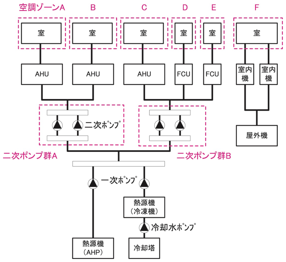
A secondary pump group refers to a collection of pumps that supply chilled water, hot water, or chilled / hot water to the same air conditioner. As shown in Figure 2-6-1 “Example of Secondary Pump Group,” when a pump system are divided into multiple pump systems and each system supplies chilled / hot water to the same air conditioner, each system is defined as one pump group.
This sheet is to be prepared in the case of central heat source-type air-conditioning systems with secondary pumps, and preparation is not required for unitary/distributed air-conditioning systems or for central heat source-type air-conditioning systems with only primary pumps.
Format of the Secondary Pump Input Sheet
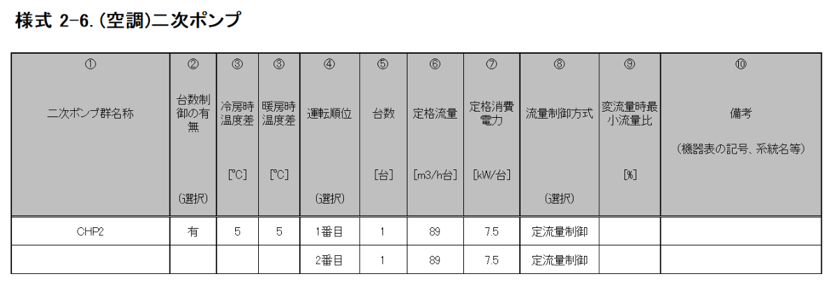
The format of the "Form 2-6. (Air Conditioning) Secondary Pump" Input Sheet is shown in Figure 2-6-2.
Input Items and Input Method of the Secondary Pump Input Sheet
The input items and input methods of the "Form 2-6. (Air Conditioning) Secondary Pump" input sheet are shown below. The numbers in brackets preceding each item correspond to the numbers in brackets shown at the top of Figure 2-6-2.
(1) Name of Secondary Pump Group
- Enter the name of the secondary pump group as an arbitrary character string. In the Energy Consumption Performance Calculation Program (Non-Residential Version), the pump group is identified by this name, so care must be taken to ensure that names are not duplicated.
- When multiple pumps form one pump group, list the specifications of each pump, enter the “Pump Group Name” for the pump entered at the top, and leave this field blank for the other pumps.
(2) Presence or Absence of Control over the Number of Devices
- If there are two or more pumps within the same pump group and the number of operating pumps is automatically controlled according to the load flow rate or load heat quantity, enter “Present.” If control over the number of devices is not performed (i.e., even when multiple pumps exist, they always operate simultaneously), enter “Absent.”
(3) Temperature Difference during Cooling / Heating
- Enter the temperature difference between the supply and return temperatures of the chilled / hot water supplied from the secondary-side air-conditioning system during cooling and heating (i.e., the designed temperature difference between supply and return) as a numerical value. The unit is °C.
- If there are pumps with different temperature differences within the same pump group, enter the temperature difference of the pump with the largest flow rate.
(4) Order of Operation
- When a secondary pump group consists of multiple secondary pumps and control over the number of devices is performed, enter the order of operation of each pump. Enter the order of operation as a character string such as “1st,” “2nd,” etc. Use half-width numbers.
- If control over the number of devices is not performed, enter “1st” for all devices.
- If one pump constitutes the pump group, enter “1st.”
(5) Number of Devices
- Enter the number of the same pumps as a numerical value.
- Note that the entered number of devices is independent of the Control over the Number of Devices entered in “(4) Order of Operation,” and all devices always operate simultaneously.
(6) Rated Flow Rate
- Enter the rated flow rate (design flow rate) per pump as a numerical value. The unit is m³/h per device.
- In the Energy Consumption Performance Calculation Program (Non-residential Version), the maximum heat supply quantity of each pump is calculated from item (3) Temperature Difference and item (6) Rated Flow Rate, and the pump load factor is obtained by dividing the daily load by the maximum heat supply quantity.
(7) Rated Power Consumption
- Enter the rated power consumption per pump as a numerical value. The unit is kW.
- The “Electric motor output” may be regarded as the power consumption.
(8) Flow Rate Control Method
- Select the flow rate control method for each pump from the options in Table 2-6-1 “List of Flow Rate Control Methods” and enter it as a character string.
| Option | Application |
|---|---|
| Constant flow control | Method in which a constant flow is always supplied |
| Rotational speed control | Method in which the pump rotational speed is controlled by an inverter, etc. |
(9) Minimum Flow Rate Ratio during Variable Flow Rate
- When “Rotational Speed Control” is selected for item (8) Flow Rate Control Method, enter the minimum flow rate setting value as a percentage (% value) of the rated flow rate (for example, when the minimum flow rate is 30% of the rated flow rate, enter “30”).
- Leave this field blank when operating at Constant Flow Rate.
(10) Remarks (Symbols, System Names, etc., in the Equipment List)
- This field is for memos during data entry and is not used in the calculation, so entry is optional.
- It is recommended to enter symbols, system names, etc., as shown in the equipment list.