Form 2-8 Total Heat Exchanger Input Sheet
The “Form 2-9 (Air Conditioning) Total Heat Exchanger" input sheet” is a sheet used to enter the design supply air volume, design return air volume, supply and return air volumes at the time of total heat exchange efficiency testing, and the effective ventilation rate under the same conditions. For total heat exchangers whose characteristic values are entered in this sheet, it becomes possible to calculate the actual operational total heat exchange efficiency more accurately without using default values.
The effective ventilation rate is a characteristic value defined in JIS B 8628 or similar testing standards for total heat exchangers, and it represents the ratio of outside air volume to the supply air volume. Even during testing, around the total heat exchange element, there exists infiltration air entering from return air to supply air and from outside the total heat exchanger to its inside (which apparently increases the measured total heat exchange efficiency). Therefore, the effective ventilation rate is measured by a test using a tracer gas. For total heat exchangers for which the necessary test results are not provided, evaluation using the “Form 2-9 (Air Conditioning) Total Heat Exchanger Input Sheet” is not possible.
Furthermore, ensuring that the ratio of the design supply air volume to the design return air volume approaches 1, i.e., setting an adequate design return air volume, contributes to increasing the actual total heat exchange efficiency and enables effective operation of the total heat exchanger. However, when applying Type 3 ventilation (mechanical exhaust ventilation) for spaces such as toilets or machine rooms, the exhaust air volume from such ventilation may be subtracted from the design return air volume of the total heat exchanger, and without design considerations, it becomes difficult to ensure an adequate design return air volume of the total heat exchanger.
When using the “Form 2-9 (Air Conditioning) Total Heat Exchanger input sheet” for the evaluation of the design primary energy consumption, it must be confirmed in the design documents that the total design outside air volume by air-conditioning and ventilation equipment and the total design exhaust air volume from indoors to outdoors are balanced (the difference must be 5% or less to meet the requirement of “balance”). In the evaluation of the balance between the total design outside air volume and the total design exhaust air volume from indoors to outdoors, the basic principle is to evaluate by floor. However, when multiple floors are integrated by an atrium or similar structure, it is acceptable to evaluate the balance collectively for multiple floors.
※Supplementary Information: Reference C2. Planning of Outside Air Volume and Exhaust Air Volume for the Evaluation of Total Heat Exchange Efficiency
Format of the Total Heat Exchanger Input Sheet
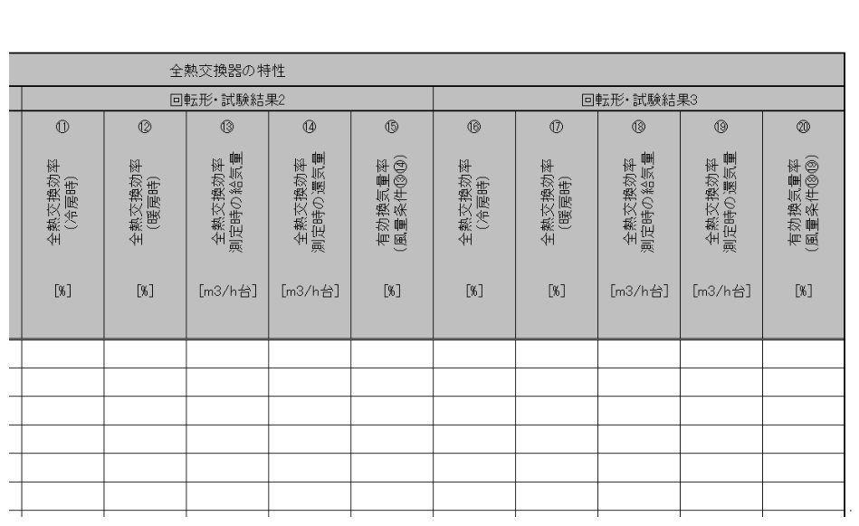
The format of “Form 2-9. (Air Conditioning) Total Heat Exchanger” input sheet is shown in Figure 2-8-1.
- ... (continued below)
- ... (continued below)
Input Items and Input Method of the Total Heat Exchanger Input Sheet
The input items and input methods of the “Form 2-9. (Air Conditioning) Total Heat Exchanger” input sheet are shown below. The numbers in brackets preceding each item name correspond to the numbers in brackets shown at the top of Figure 2-8-1.
(1): Name of Total Heat Exchanger
- Enter the name of the total heat exchanger described in item (16) of the "Form 2-7. (Air Conditioning) Air Conditioner" input sheet. From item (2) onward, enter information related to that total heat exchanger.
- Even for the same product, if the “(3): Design Outside Air Volume or Design Supply Air Volume” or “(4) Design Exhaust Air Volume or Design Return Air Volume” differs, assign a different total heat exchanger name.
(2) Type of Total Heat Exchanger
- Select either “Stationary Type” or “Rotary Type.”
(3) Design Outside Air Volume or Design Supply Air Volume
- Enter the design value of the outside air volume taken in from outdoors by the total heat exchanger, or the supply air volume discharged from the total heat exchanger into the room. The unit is m³/h per device.
(4) Design Exhaust Air Volume or Design Return Air Volume
- Enter the design value of the exhaust air volume discharged from the total heat exchanger to outdoors or indoors, or the return air volume taken in from the room by the total heat exchanger. The unit is m³/h per device.
(5) Number of Devices
- Enter the number of this total heat exchanger installed in the evaluated building. This value must match the total number of the relevant total heat exchanger entered in item “(2) Number of Devices” of Form 2-7.
(6) Total Heat Exchange Efficiency (during Cooling)
(7) Total Heat Exchange Efficiency (during Heating)
- The testing methods and indoor/outdoor air conditions at the time of testing shall follow the same requirements as items (18) and (19) of the "Form 2-7. (Air Conditioning) Air Conditioner" input sheet. For stationary total heat exchangers, JIS B 8628:2003 cannot be applied.
- For equipment provided with airflow adjustment devices (switches for high/low-speed operation, etc.), enter the total heat exchange efficiency measured at an airflow rate equal to or higher than the design airflow rate. Design documents shall clearly indicate, together with the design airflow rate, the airflow rate and total heat exchange efficiency at the time of testing, as stated in the catalog, technical data, or specifications of the total heat exchanger.
- For rotary total heat exchangers, enter the total heat exchange efficiency measured with face-velocity conditions (m/s) equal to or greater than the face-velocity conditions at the design airflow rate. Here, “face velocity” refers to the value obtained by dividing the airflow rate (m³/h) by “face area of total heat exchanger (m²) × 0.5 × 3600 (s/h).”
- Enter the test result relating to total heat exchange efficiency. The unit is %. When the product’s test result includes decimal values, round to one decimal place and enter it.
(8) Supply Air Volume at Time of Total Heat Exchange Efficiency Measurement
(9) Return Air Volume at Time of Total Heat Exchange Efficiency Measurement
(10) Effective Ventilation Rate (for Airflow Conditions (8) and (9))
- As conditions when the test results of (6) and (7) were measured, enter the supply air volume, return air volume, and effective ventilation rate. The units are m³/h per device and %. When the product’s test result includes decimal values, round to one decimal place and enter it.
- For stationary total heat exchangers, it is sufficient to enter items (6) through (10).
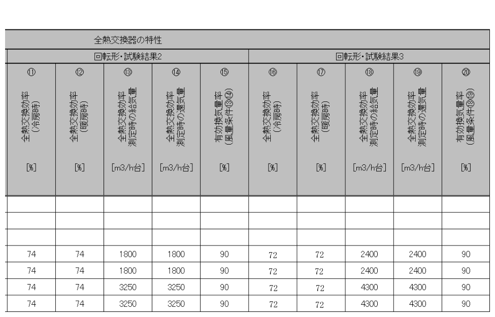
- For rotary total heat exchangers, after entering items (6) through (10), also enter the second and third test results in the subsequent fields from (11) onward. Enter the test results in the order from the smaller airflow condition.
- For rotary total heat exchangers, enter the test results for the second (for items (11)–(15)) and third (for items (16)–(20)) airflow conditions for supply air and return air.
(11) Total Heat Exchange Efficiency (during Cooling)
(12) Total Heat Exchange Efficiency (during Heating)
(13) Supply Air Volume at Time of Total Heat Exchange Efficiency Measurement
(14) Supply Air Volume at Time of Total Heat Exchange Efficiency Measurement
(15) Effective Ventilation Rate (for Airflow Conditions (13) and (14))
(16) Total Heat Exchange Efficiency (during Cooling)
(17) Total Heat Exchange Efficiency (during Heating)
(18) Supply Air Volume at Time of Total Heat Exchange Efficiency Measurement
(19) Supply Air Volume at Time of Total Heat Exchange Efficiency Measurement
(20) Effective Ventilation Rate (for Airflow Conditions (18) and (19))
- In the Energy Consumption Performance Calculation Program (Non-Residential Version) Standard Input Method, for rotary total heat exchangers, the effective total heat exchange efficiency under the design airflow condition is calculated based on the first through third test results and is used in the calculation of the design primary energy consumption.
- For rotary total heat exchangers, the “(3): Design Outside Air Volume or Design Supply Air Volume” must fall between the supply air volumes at the first and third measurements, and the “(4) Design Exhaust Air Volume or Design Return Air Volume” must fall between the return air volumes at the first and third measurements. In other words, when the design airflow is smaller or greater than the range of airflow conditions obtained during tests, calculation of the effective total heat exchange efficiency using Form 2-9 cannot be performed.