Form 2-7 Air Conditioner Input Sheet
In the "Form 2-7 (Air Conditioning) Air Conditioner" input sheet, based on the air conditioner drawings (equipment list, system diagram, floor plan, automatic control diagram, etc.) describing the specifications of air conditioners, enter information on the cooling and heating capacities, supply air volume, power consumption of each fan of air conditioner group (air handling units, fan coil units, packaged air conditioners, total heat exchangers, etc.), and efficiency and control methods (airflow rate control, outside air cut control, and outside air cooling control) of total heat exchangers, as well as the names of the secondary pump group and the heat source group connected to the air conditioner group.
The definition of an air conditioner group is as follows.
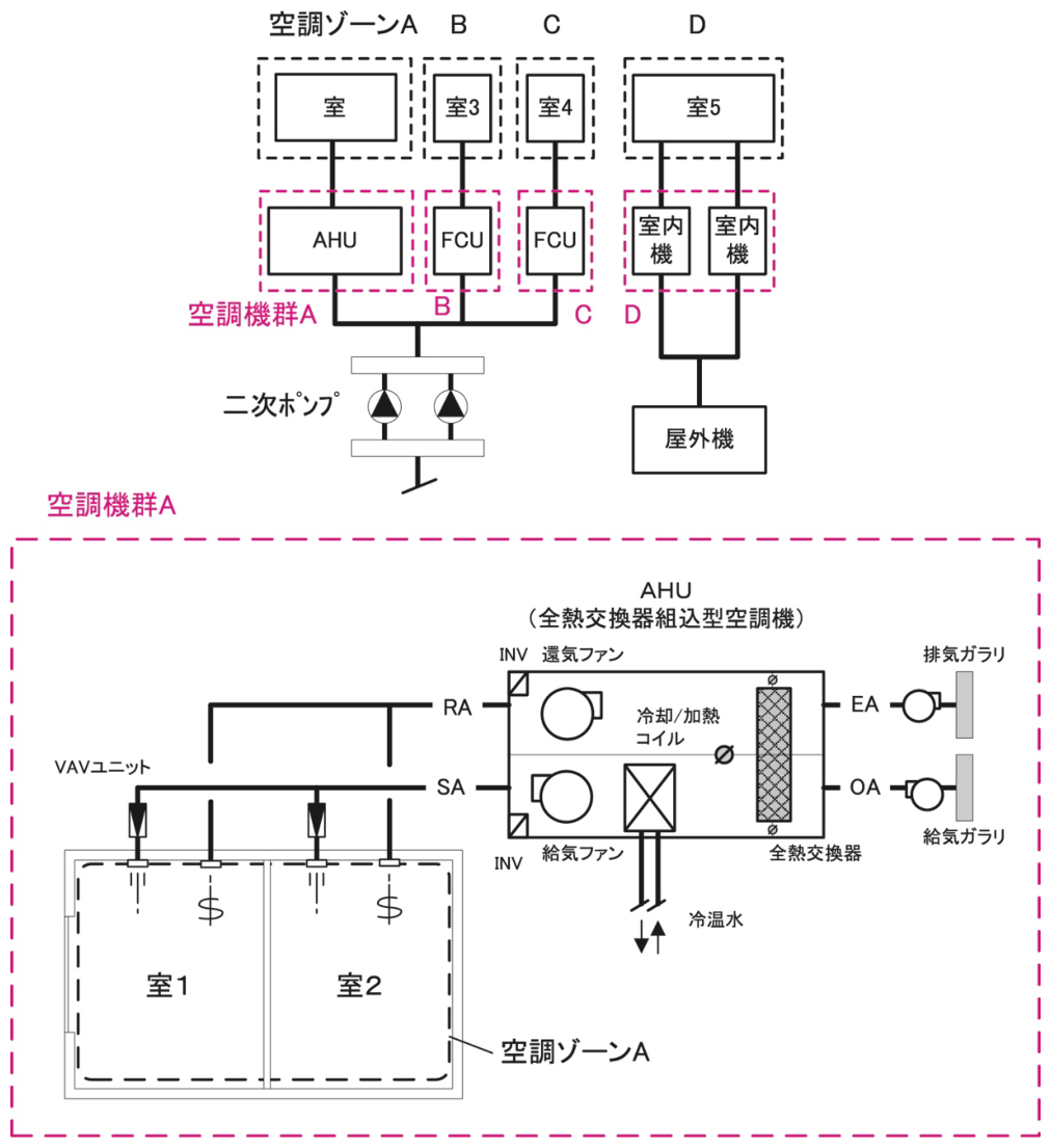
For indoor units of packaged air conditioners, define the air conditioner group for each outdoor unit system. However, if multiple indoor units belonging to the same outdoor unit system are installed in separate air-conditioned zones, group the indoor units by air-conditioned zone and define each as one air conditioner group.
Even when air conditioners of the same specification on a typical floor are connected to the same secondary pump group and the same heat source group, in principle, the air conditioners on each floor shall be defined separately as individual air conditioner groups.
Format of the Air Conditioner Input Sheet
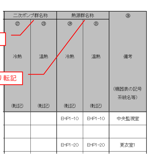
The format of “Form 2-7. (Air Conditioning) Air Conditioner” input sheet is shown in Figure 2-7-2.
- ... (continued below)
- ... (continued below)
Input Items and Input Method of the Air Conditioner Input Sheet
The input items and input methods of the “Form 2-7. (Air Conditioning) Air Conditioner” input sheet are shown below. The numbers in brackets preceding each item name correspond to the numbers in brackets shown at the top of Figure 2-7-2.
For sensible heat exchangers, select “Fan” for “(3) Air Conditioner Type,” enter values only in “(2) Number of Devices,” the applicable fields among (7) through (10) “Fan Rated Power Consumption,” “(13) Presence or Absence of the “Stop Outside Air Introduction During Preheating” process, and “(21) Rotor Power Consumption” (only for rotary type) of fields relating to total exchangers.
(1) Name of Air Conditioner Group
- Enter the name of the air conditioner group using any character string. In the Energy Consumption Performance Calculation Program (Non-Residential Version), the air conditioner group is identified by this name, so care must be taken to ensure that names are not duplicated.
- When multiple air conditioner devices form one air conditioner group, list the specifications of each air conditioner consecutively; enter the “Name of Air Conditioner Group” for the air conditioner entered at the top, and leave the fields for other air conditioners blank.
(2) Number of Devices
- Enter the number of air conditioners as a numerical value.
(3) Air Conditioner Type
- Select the type from the options shown in Table 2-7-1 “List of Air Conditioner Type” and enter it as a character string.
| Option | Application |
|---|---|
| Air handling unit | Air handling units, outdoor air handling units, etc. |
| FCU | Fan coil units, fan convectors, etc. |
| Indoor unit | Indoor units of packaged air conditioners (EHP, GHP, KHP, WHP, etc.) |
| Total heat exchanger unit | Individually installed total heat exchanger units (including units with direct-expansion coils) |
| Fan | Fans handled in the air-conditioning calculation (supply/exhaust fans interlocked with air conditioning, and fans that are not interlocked but affect the supply/exhaust balance of rooms subject to air-conditioning calculation, etc.) |
| Radiator | Panel radiators, etc. |
| Ceiling radiant heating/cooling panel | Ceiling radiant heating/cooling panel |
(4)(5) Rated Cooling (Space Cooling) Capacity / Rated Heating (Space Heating) Capacity
- Enter the rated cooling (space cooling) capacity and rated heating (space heating) capacity per air conditioner as numerical values. The unit is kW/device.
- When air conditioner type is “Air Conditioner” or “FCU”, capacities are determined by the design flow rate of chilled/hot water; therefore, enter the required cooling (space cooling) capacity and heating (space heating) capacity listed in the equipment list of design drawings. For indoor units of packaged air conditioners, enter capacities under the standard rated conditions prescribed in JIS, etc. (conditions such as chilled/hot water temperature, cooling water temperature, and flow rate).
- If a direct-expansion coil is installed in the total heat exchanger unit, enter the cooling and heating capacities of the coil.
- When a chilled/hot water coil is installed in the supply air duct of an outside air handling unit, select “Air Conditioner” as the air conditioner type and enter the cooling and heating capacities of the coil.
- For ceiling radiant heating/cooling panels, enter the rated cooling capacity (temperature difference of 8 K between indoor temperature and mean water supply temperature) and rated heating capacity (temperature difference of 15 K between indoor temperature and mean water supply temperature) tested in accordance with the Ceiling Radiant Cooling and Heating Panel Performance Test Standard (ARCH 2017 CHTRS) established by the Association of Radiant Cooling and Heating systems of Japan (ARCH).
(6) Design Maximum Outside Airflow Rate
- Enter the design maximum outside airflow rate per air conditioner in numerical value. The unit is m³/h per device.
- This value is used as the upper limit of the outside air introduction volume during outside air cooling control. If “(14): Presence or Absence of Outside Air Cooling Control” described later is “Absent,” it is not necessary to enter this value.
(7)(8)(9)(10) Supply Fan Rated Power Consumption
- Enter the rated power consumption of each fan by type (supply, return, outside, exhaust) in numerical values. The unit is kW/device.
- When selecting “Radiator” or “Ceiling Radiant Heating/Cooling Panel” as the air conditioner type, enter the power consumption of pumps, etc., used to transfer heat to the panel, etc.
- The “Electric motor output” may be regarded as the power consumption.
- For unitary / distributed air-conditioning systems (such as packaged air conditioners, gas-engine heat pump cooling / heating units, and room air conditioners) in which only the outdoor unit (or only the indoor unit) is powered, as a rule, enter the total power consumption of the outdoor and indoor units in “(11): Heat Source Main Module Rated Energy Consumption” on Form 2-5 “Heat Source Input Sheet,” and enter “0” in “(7)(8)(9)(10): Supply Fan Rated Power Consumption” on Form 2-7 (Air Conditioning) “Air Conditioner Input Sheet.”
- Although power consumption is entered by fan type, it is totaled in energy calculation as the overall fan rated power consumption. Therefore, while exact classification is not strictly required for entry, it is recommended to enter values reasonably categorized to facilitate cross-checking with the drawings by examiners.
(11) Airflow Rate Control Method
- Select the airflow rate control method for each air conditioner from the options in Table 2-7-2 “List of Airflow Rate Control Methods” and enter it as a character string.
- “Rotational Speed Control” applies only to systems that “automatically” change fan speed according to indoor temperature, etc. Manual airflow rate switching commonly found in FCUs or indoor units is not subject to this item.
| Option | Application |
|---|---|
| Constant air volume control | When the fan rotational speed is always constant |
| Rotational speed control | Control in which the fan rotational speed is automatically controlled by an inverter, etc. according to room temperature, etc., to vary the air volume. |
(12) Minimum Airflow Ratio at Variable Airflow Rate
- If rotational speed control is applied, enter the ratio (%) of the minimum airflow rate setting value to the rated airflow rate (e.g., enter “30” if the minimum airflow rate is 30% of the rated airflow rate).
- Leave this field blank when operating at Constant Airflow Rate.
(13) Presence or Absence of the "Stop Outside Air Introduction During Preheating" process
- Enter “Present” if the “Stop Outside Air Introduction During Preheating” process (outside air cut control, warming-up control) is implemented; otherwise, enter “Absent.” Here, "Stop Outside Air Introduction During Preheating" process is defined as a control that stops outside air introduction to reduce the outside air load when the air conditioner starts up while nobody is in the room.
(14) Presence or Absence of Outside Air Cooling Control
- Enter “Present” if outside air cooling control is implemented; otherwise, enter “Absent.” Here, outside air cooling control is defined as a control that, during cooling operation, introduces more outside air than the required fresh air volume when the enthalpy of outside air is lower than that of indoor air, thereby reducing coil heat load. However, in primary energy consumption calculation, the maximum value of outside air introduction is regarded as the rated airflow rate of the supply air fan entered in “(6): Design Maximum Outside Airflow Rate.”
(15) Presence or Absence of a Total Heat Exchanger, and Inclusion in Form 2‑9
- Enter one of the three options indicating whether a total heat exchanger is installed in the relevant air conditioner group and whether Form 2-9 (Total Heat Exchanger Input Sheet) is used when installed.
| Option | Application |
|---|---|
| Without total heat exchanger | When no total heat exchanger is installed in the air conditioner group |
| With total heat exchanger, entered in Form 2-9 | When a total heat exchanger is installed in the air conditioner group and its characteristic values are entered using Form 2-9. |
| With total heat exchanger, not entered in Form 2-9 | When a total heat exchanger is installed in the air conditioner group but its characteristic values are not entered using Form 2-9 |
- In the Energy Consumption Performance Calculation Program (Non-residential), in order to take actual operating performance into account, the air-conditioning load calculation uses the corrected total heat exchange efficiency η′ obtained by multiplying the entered total heat exchange efficiency η by the following three correction coefficients: Ctol, Ceff, Cbal.
Ctol: Coefficient related to displayed value
Ceff: Coefficient related to effective ventilation rate (1 – ((1/e) – 1) × (1 – η)/η)
e: Effective ventilation rate
Cbal: Coefficient related to balance between supply and exhaust air volumes
- Each correction coefficient is determined as shown in Table 2-7-4.
| Entry in Form 2-9 | Ctol | Ceff | Cbal |
|---|---|---|---|
| Yes | Fixed at 0.95 | Calculated from the effective ventilation rate (Form 2-9) | Calculated from the air volume (Form 2-9) |
| No | Calculated assuming an effective ventilation rate of 0.85 | Fixed at 0.67 |
(16) (When described in Form 2-9 Total Heat Exchanger Input Sheet) Name of Total Heat Exchanger
- Assign a unique name to each total heat exchanger installed, in order to link it with the characteristic values described in Form 2-9. When the same product has the same design airflow rate, use the same name; when the design airflow rate differs, use a different name.
- The entered name must correspond to “(1) Name of Total Heat Exchanger” in “Form 2-9 Total Heat Exchanger Input Sheet”.
(17) Design Airflow Rate of Total Heat Exchanger
- Enter as a numerical value the airflow rate passing through the total heat exchanger (the airflow rate assumed to be realized through duct pressure-loss calculation and initial adjustment). The unit is m³/h per device. Enter the airflow rate per air conditioner.
- When the supply airflow rate and exhaust airflow rate differ, enter the supply airflow rate.
- Even when “Total Heat Exchanger Present / Described in Form 2-9” is selected in (15), entry in (17) is required.
(18) Total Heat Exchange Efficiency (during Cooling)
(19) Total Heat Exchange Efficiency (during Heating)
- The indoor and outdoor air conditions for the tests of total heat exchange efficiency (enthalpy exchange efficiency) during cooling and heating shall comply with Annex 4, Table 3 of JIS B 8628:2003, or T3 of Table 1 and T6 of Table 2 of JIS B 8639:2017 (During Cooling: outdoor dry-bulb 35 °C / wet-bulb 31 °C; indoor dry-bulb 27 °C / wet-bulb 20 °C. During Heating: outdoor dry-bulb 5 °C / wet-bulb 3 °C; indoor dry-bulb 20 °C / wet-bulb 15 °C).
- For stationary total heat exchangers, the testing methods for total heat exchange efficiency shall comply with JIS B 8628:2003, JIS B 8628:2017, JIS B 8639:2017, ISO 16494:2014, or equivalent standards. For rotary total heat exchangers, the testing methods for total heat exchange efficiency shall comply with ISO 21773:2021, EUROVENT RS8/C/002-2019, ANSI/ASHRAE Standard 1061, or equivalent standards. Note that, when using Form 2-9 Total Heat Exchanger Input Sheet, test results obtained in accordance with JIS B 8628:2003 cannot be used.
- For equipment provided with airflow adjustment devices (switches for high/low-speed operation, etc.), enter the total heat exchange efficiency measured at an airflow rate equal to or higher than the design airflow rate. Design documents shall clearly indicate, together with the design airflow rate, the airflow rate and total heat exchange efficiency at the time of testing, as stated in the catalog, technical data, or specifications of the total heat exchanger.
- For rotary total heat exchangers, enter the total heat exchange efficiency measured with face-velocity conditions (m/s) equal to or greater than the face-velocity conditions at the design airflow rate. Here, “face velocity” refers to the value obtained by dividing the airflow rate (m³/h) by “face area of total heat exchanger (m²) × 0.5 × 3600 (s/h).”
- Enter the test result relating to total heat exchange efficiency. The unit is %. When the product’s test result includes decimal values, round to one decimal place and enter it.
- Even when “Total Heat Exchanger Present / Described in Form 2-9” is selected in (15), entries in (18) and (19) are required.
(20) Presence or Absence of Automatic Ventilation Switching Function
- Enter “Present” if the automatic ventilation switching function is adopted, and “Absent” if it is not.
- The automatic ventilation switching function refers to a function that automatically switches between heat-exchange ventilation and normal ventilation (bypassing the total heat exchange element or stopping its rotation, including rotational speed control) based on the temperature and humidity of the outdoor and indoor air, thereby reducing the air-conditioning load.
- If the switching is performed manually, enter “Absent,” (For example, in cases where individually installed total heat exchangers have a “ventilation operation” function without heat exchange that is switched manually, enter “Absent.”)
(21) Rotor Power Consumption
- If the total heat exchanger is of the rotary type, enter the rotor power consumption in numerical value. The unit is kW/device.
- If the rotor power consumption is unknown, the rated output of the electric motor driving the rotor may be entered.
- For the stationary type, leave the field blank, as there is no motor.
(22) Name of Secondary Pump Group (Cooling Heat)
(23) Name of Secondary Pump Group (Heating Heat)
- Select and enter, as a character string, the Name of Secondary Pump Group that supplies cooling heat and heating heat to each air conditioner group from among the names entered in “the format of Form 2-6 (Air Conditioning) ‘Secondary Pump Input Sheet’” shown in Figure 2-6-2.
- The Name of Secondary Pump Group must be identical to that in the "Secondary Pump Input Sheet".
(24) Name of Heat Source Group (Cooling Heat)
(25) Name of Heat Source Group (Heating Heat)
- Select and enter, as a character string, the Name of Heat Source Group that supplies cooling heat and heating heat to each air conditioner group from among the names entered in “the format of Form 2-5 (Air Conditioning) ‘Heat Source Input Sheet’” shown in Figure 2-5-2.
- The Name of Heat Source Group must be identical to that in the "Heat Source Input Sheet".
(26) Remarks (Symbols, System Names, etc., in the Equipment List)
- This field is for memos during data entry and is not used in the calculation, so entry is optional.
- It is recommended to enter equipment numbers (symbols) or system names, etc., for equipment names, as indicated in the design drawings.