2.1–2.3 Scope and Calculation Conditions
2.1 Introduction
2.1.1 Scope of Application
The air conditioning equipment to be included in the calculations is as follows.
-
Air conditioning equipment with the following three functions
- Air purification (functions to comply with the standards for dust amount, CO concentration, CO2 concentration, etc. as specified in Article 129-2-6 of the Enforcement Order of the Building Standards Act)
- Temperature and humidity control (functions to comply with the reference ranges)
- Airflow rate adjustment
-
Fan for air conditioning
- Fans and total heat exchangers installed in the rooms to be air-conditioned, for bringing fresh outside air
- Fans for exhausting air corresponding to the outside air supplied to the air-conditioned room
-
Individually distributed air conditioners such as variable refrigerant flow (VRF) system and room air conditioners
- Dedicated heating equipment and dedicated cooling equipment
- Various types of fans that work in conjunction with air conditioners (fans for introducing outside air installed in the middle of ducts, fans for exhausting excess air from occupied rooms, etc.), circulating fans (air curtains, ceiling fans, etc.), fans for airflow windows and push-pull windows, etc.
The following air conditioning equipment is not included in the calculation as air conditioning equipment.
- Air conditioning systems installed for cooling spaces that are typically ventilated, such as electrical rooms and elevator machine rooms. These are considered as mechanical ventilation equipment.
- Air conditioning equipment installed in the kitchen. The energy consumption of the fan power for air supply and exhaust is calculated as mechanical ventilation equipment.
Here, this calculation method determines the room heat load (total heat load) required to maintain the set temperature and humidity. While it estimates the humidification (or dehumidification) load itself, the calculation assumes that the total heat, including the load for humidification and dehumidification, is processed by the heat source device. Therefore, it does not provide a rigorous evaluation. To accurately assess the performance of a humidification system, it is necessary to separate sensible heat and latent heat and perform more precise calculations. However, this remains a topic for future consideration.
2.1.2 Definition of Terms
2.1.2.1 Air Conditioning Equipment
Equipment used to simultaneously process air temperature, humidity, cleanliness, and airflow distribution to meet the requirements of the target space.
2.1.2.2 Air Handling Unit Group
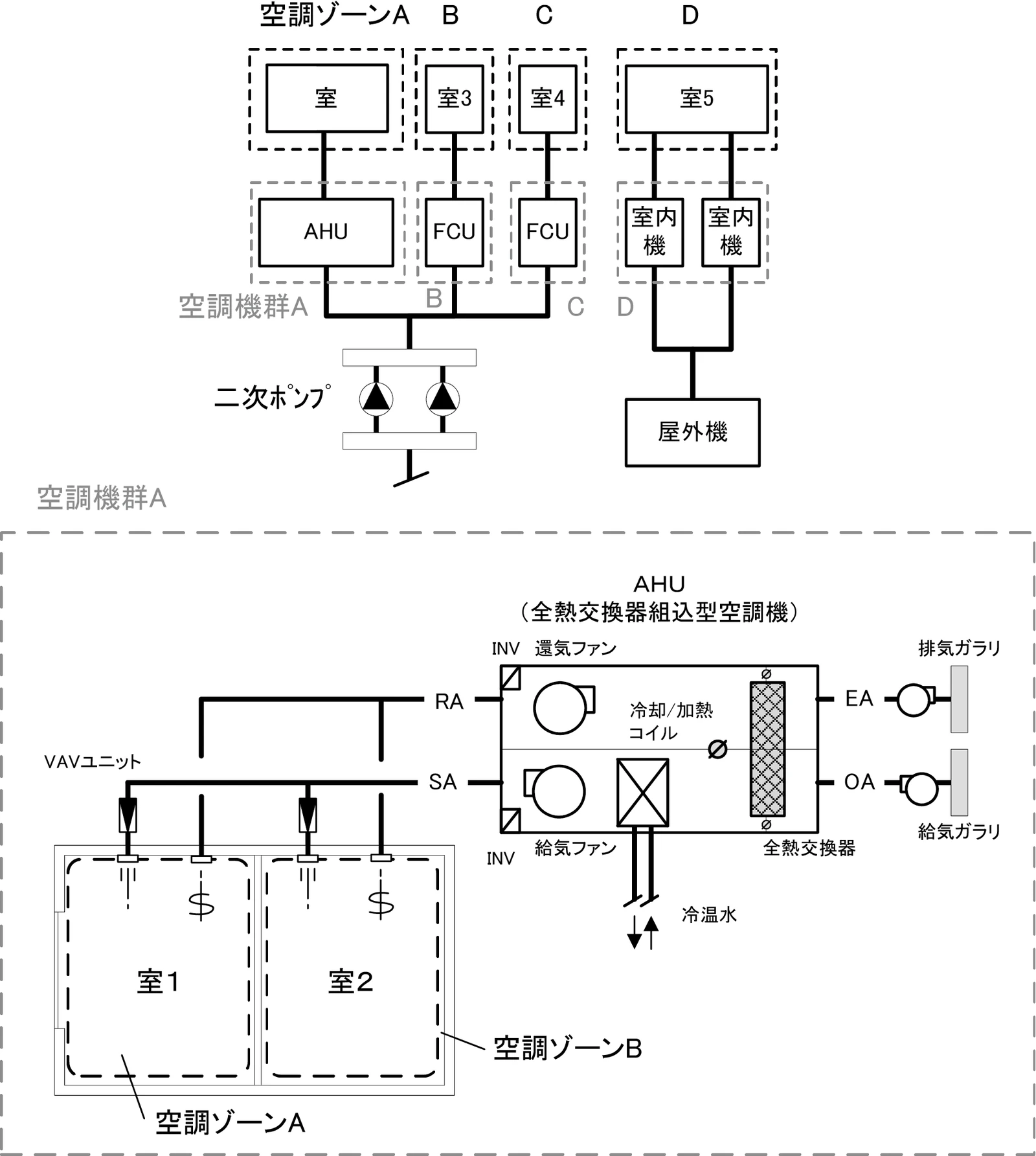
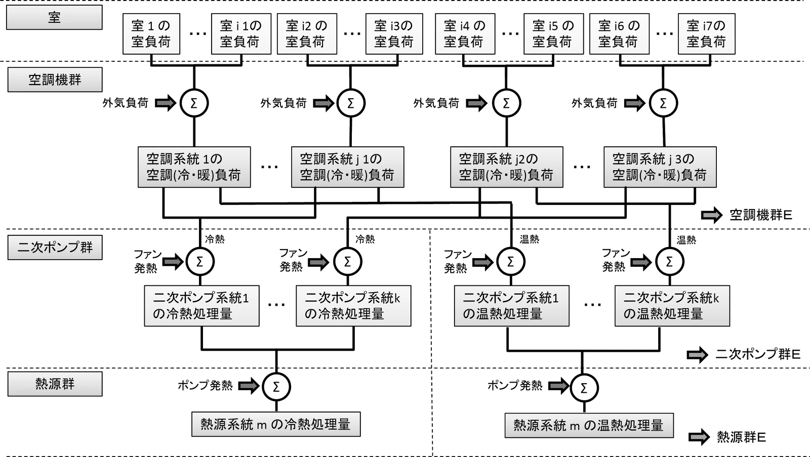
It is a collection of air handling units and indoor units of packaged air conditioners and the other related devices. As shown in Figure 2.1.2.1, it is defined as a series of systems for supplying cooled or heated air or fresh outside air to the target air conditioning zone. The following equipment are defined as a same group; Total heat exchangers that work in conjunction with air handling units and indoor units, Various types of fans (such as fans installed in the middle of ducts for introducing outside air and fans for exhausting excess air from occupied rooms), Circulating fans (air curtains, ceiling fans, etc.), Fans for airflow windows and push-pull windows, etc.
2.1.2.3 Secondary Pump Group
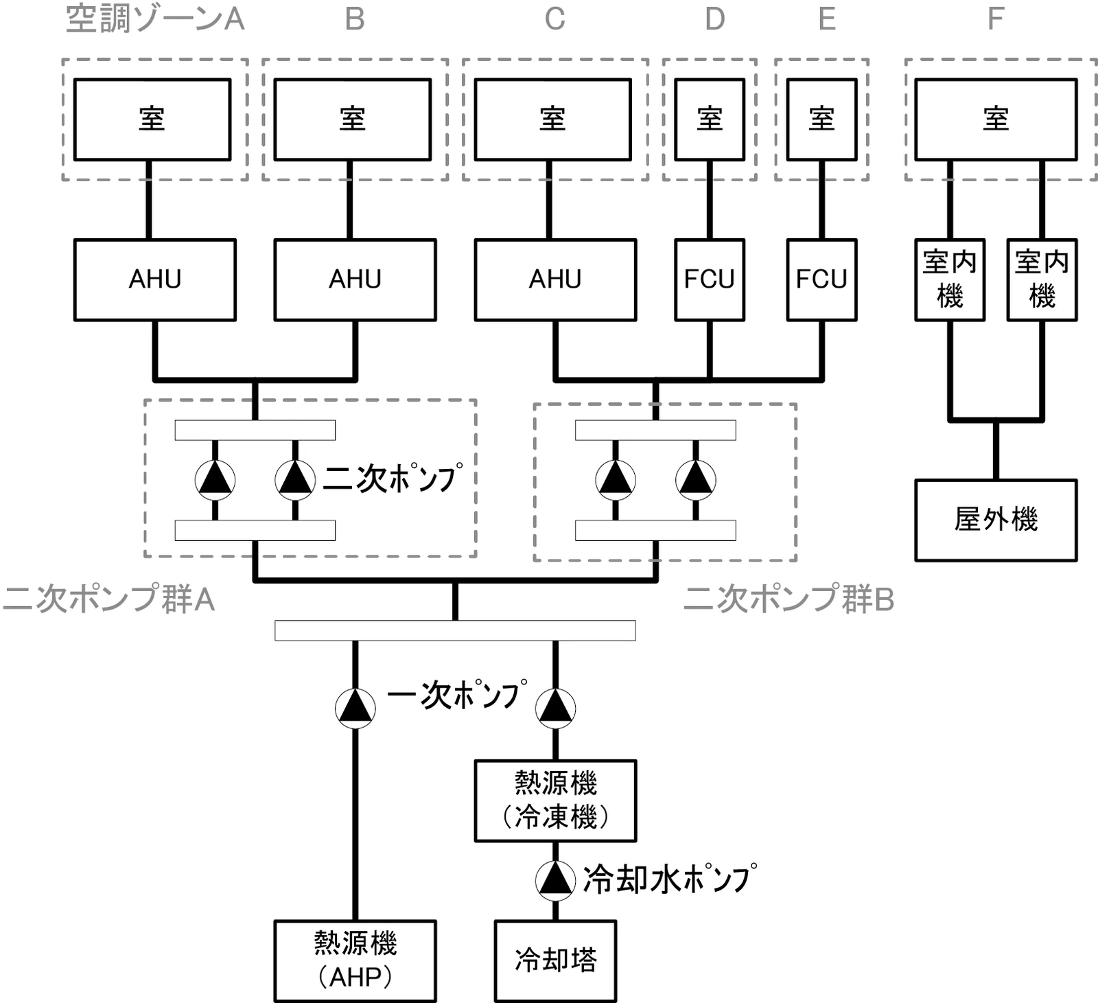
It is a collection of secondary pumps that supply chilled or hot water to a same air handling unit group. As shown in Figure 2.1.2.2, if a pump system is divided into multiple branches, each system is defined as one pump group. For air conditioning systems with individually distributed systems (packaged air conditioners) or central heat source systems with only primary pumps, there may be no secondary pump group.
2.1.2.4 Heat Source Group
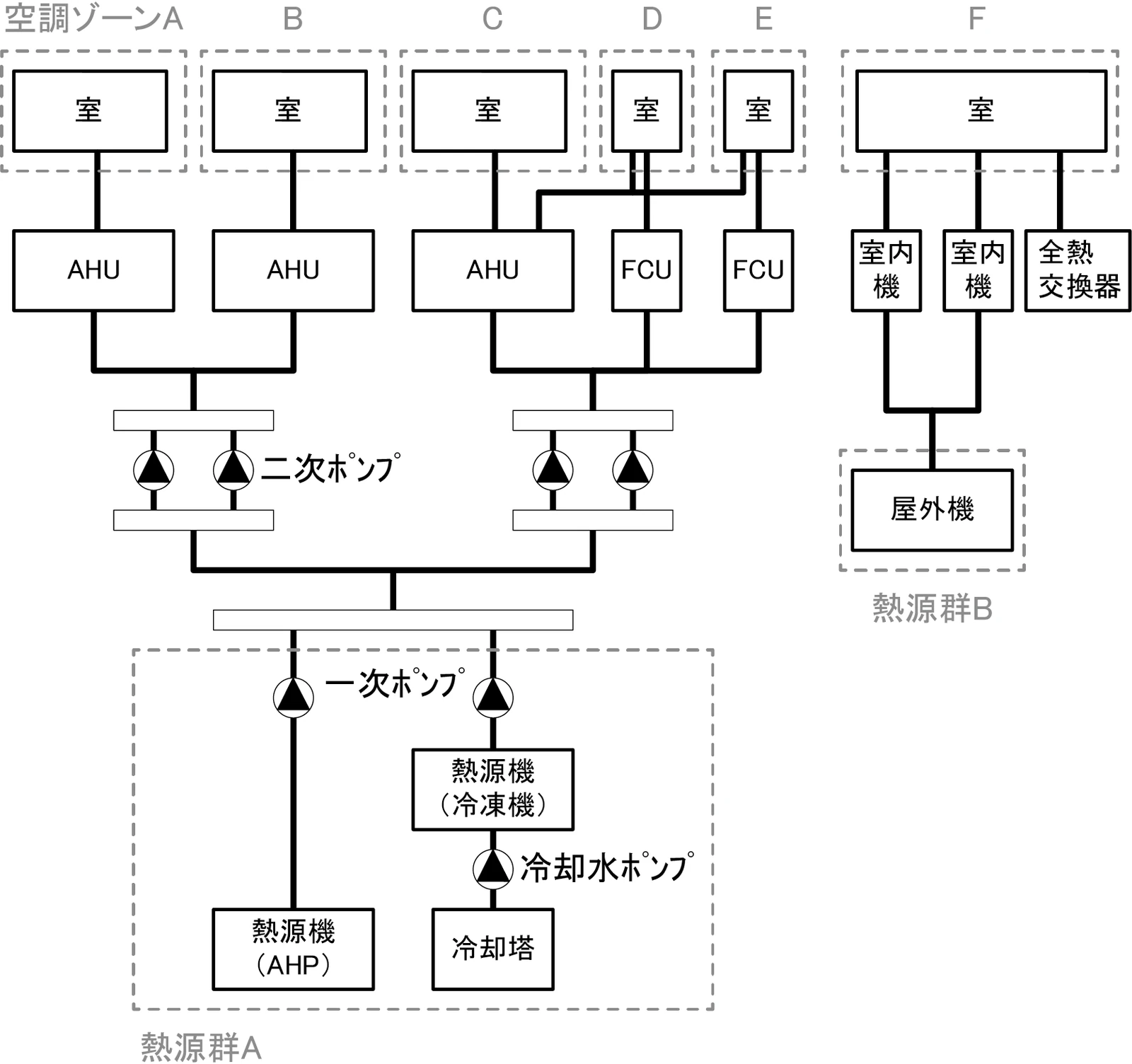
It is a collection of heat source equipments that generate chilled or hot water. As shown in Figure 2.1.2.3, for a central heat source system, it is defined as multiple heat source system equipment (heat source unit, primary pump, cooling tower, cooling water pump, thermal storage pump, etc.) that work together, and for an individually distributed air conditioning system, it is defined as outdoor units of a packaged air conditioner.
2.1.2.5 Load Factor Range
In this calculation method, the number of hours each device runs (hereinafter referred to as the "number of hours of load factor occurrences") at what load factor (the amount of heat processed by each device divided by the rated capacity of each device) is calculated. And then based on this value, the energy consumption is calculated. In this calculation method, the load factor is classified into 11 ranges consisting of 10 ranges of 0 to 0.1, 0.1 to 0.2, ..., 0.9 to 1.0 in increments of 0.1, and another range of load factors: of 1 or more. This division of load factors is called a load factors range and the load factor range of this calculation method is totalized for 11 ranges.
2.1.2.6 Outside Air Temperature Range
In the calculation of energy consumption for a heat source group, "number of hours of load factor occurrences" should be totalized after classified not only by load factor range but also by outside air temperature. The range of outside air temperature used to totalize load factors is called the outside air temperature range.
2.1.2.7 Automatic Ventilation Switching Function for Total Heat Exchanger
It means the control function to automatically take in outside air directly into the room in a system using total heat exchangers, when it is determined that the air conditioning load can be reduced by taking in outside air directly without the total heat exchange based on the relationship between outside air temperature and inside air temperature, outside air temperature and humidity and inside air temperature and humidity, outside air enthalpy and inside air enthalpy, etc. For example, when controlling with enthalpy, if the enthalpy of outside air is lower than that of inside air during cooling or higher during heating, outside air is directly introduced into the room without performing total heat exchange. There are several types of control methods, but in this calculation method, energy consumption is calculated assuming that it is controlled based on the enthalpies of outside air and inside air.
2.1.2.8 Outside Air Cooling Control
It means the control function to automatically introduce more outside air than the required fresh outside air volume during cooling operation when the outside air enthalpy is lower than the inside air enthalpy, thereby reducing the amount of processing cooled air through the coils. In general, whether or not to introduce outside air is often determined by considering also conditions other than enthalpy, such as the outside air temperature being below the room temperature, the outside air temperature being above the set minimum temperature, and the outside air humidity being below the set humidity. However, for simplicity, this calculation method calculates energy consumption by assuming that only enthalpy is used for control. The maximum value of outside air volume is assumed to be the rated airflow rate of the supply air fan.
2.1.2.9 Control to Stop Outside Air Introduction During Precooling or Preheating
It means the control function to automatically stop the introduction of outside air when there is no person in a room at the startup phase of air conditioning to reduce the outside air load (also called "Warm-up Control").
2.1.2.10 Control over the Number of Devices
For example, for secondary pumps, this refers to a control in which there are two or more pumps in the secondary pump group and the number of pumps in operation is automatically changed according to the load.
2.1.2.11 Rotational Speed Control
For example, in the case of a secondary pump, this refers to a control system in which the pump rotation speed is automatically changed by an inverter or other devices.
2.1.3 Calculation Flow
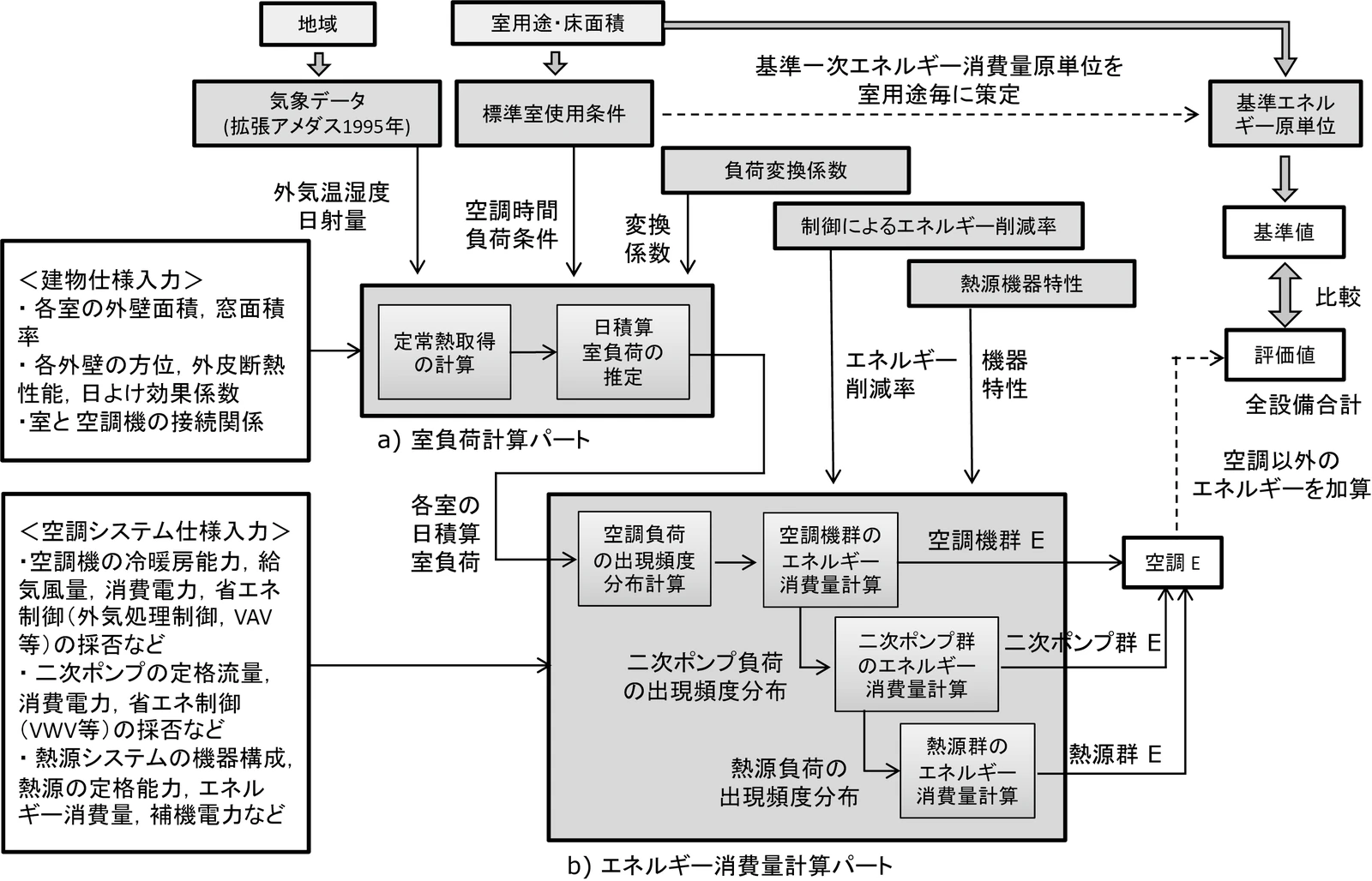
Figure 2.1.3.1 shows the calculation flow of energy consumption for air conditioning equipment. The calculation can be divided into two parts: a) room load calculation part, and b) energy consumption calculation part. The energy consumption of the air handling unit group, secondary pump group, and heat source group is calculated as a function of the loads handled by these units (assumed to be the air conditioning load, secondary pump load, and heat source load, respectively), and these loads can be obtained from the room load of each room. Figure 2.1.3.2 shows the process of calculating the load of each equipment from the room load. First, calculate the room load for each room. Next, calculate the total room load for each air handling unit group for each target room. And then calculate the air conditioning load for each air handling unit group by adding the outside air load to above room load. Similarly for the secondary pump group, calculate the total air conditioning load of the air handling unit group for which the relevant secondary pump group conveys chilled/hot water. And then, calculate the secondary pump load by adding the heat generation of the air conditioner fan to above air conditioning load. For a heat source group, calculate the total secondary pump load of the secondary pump group for which the relevant heat source group supplies heat. And then, calculate the heat source load by adding the heat generation of the secondary pump to above secondary pump load.
Although the heat generation by primary pumps should be included in the heat source load, the heat generation by primary pumps is not included in this calculation because it would require repetitive calculations, which would complicate the logic.
2.2 Weather Conditions
2.2.1 Weather Data
For weather data, use the Expanded AMeDAS Weather Data, reference year 1995 edition (based on 1981-1995 data). This weather data can be purchased from the website of Meteorological Data System Co., Ltd. ( here ).
| Variable Name | Description | Unit | Reference |
|---|---|---|---|
\(ClimateZone\) |
Climate zone of the location of the building subject to evaluation |
- |
Form 0: (5) Regional Categories in Buildling Energy Codes |
| Variable Name | Description | Unit | Reference |
|---|---|---|---|
\(\theta_{oa,d,t}\) |
Outside air temperature at date \(d\), time \(t\) |
℃ |
2.2.3, 2.2.4 |
\(X_{oa,d,t}\) |
Absolute humidity at date \(d\), time \(t\) |
kg/kgDA |
2.2.4 |
\(S_{dsr,d,t}\) |
Direct Normal Irradiance at date \(d\), time \(t\) |
W/m2 |
2.4.1 |
\(S_{isr,d,t}\) |
Horizontal sky solar radiation at date \(d\), time \(t\) |
W/m2 |
2.4.1 |
\(S_{nsr,d,t}\) |
Horizontal Long-wavelength Radiation at date \(d\), time \(t\) |
W/m2 |
2.4.1 |
\(lati\) |
Latitude |
° |
2.4.1 |
\(longi\) |
Longitude |
° |
2.4.1 |
The Buildling Energy Codes define climate zones (region 1-8), and specify the category of each city, ward, town, and village.
For each climate zone, the weather data to be used are specified in the table below. For example, for the region 1, the weather data file for "Hokkaido/Kitami" is used. The calculation method uses the outside air temperature, absolute humidity, direct normal irradiance, horizontal sky solar radiation, and horizontal long-wavelength radiation at date \(d\) and time \(t\) from the weather data file for the relevant representative location.
In addition, the values specified in the table below should be used for latitude \(lati\) and longitude \(longi\).
| Climate zone | Weather data (representative location) | Cooling Degree Days (24-24) | Heating Degree Days (18-18) | Latitude | Longitude |
|---|---|---|---|---|---|
Region 1 |
Kitami, Hokkaido |
12 |
4613 |
43.82 |
143.91 |
Region 2 |
Iwamizawa, Hokkaido |
2 |
4054 |
43.21 |
141.788 |
Region 3 |
Morioka, Iwate |
25 |
3234 |
39.695 |
141.168 |
Region 4 |
Nagano, Nagano |
77 |
2887 |
36.66 |
138.195 |
Region 5 |
Utsunomiya, Tochigi |
92 |
2325 |
36.547 |
139.872 |
Region 6 |
Okayama, Okayama |
240 |
1822 |
34.658 |
133.918 |
Region 7 |
Miyazaki, Miyazaki |
256 |
1255 |
31.935 |
131.417 |
Region 8 |
Naha, Okinawa |
515 |
125 |
26.203 |
127.688 |
2.2.2 Cooling/Heating Season
| Variable Name | Description | Unit | Reference |
|---|---|---|---|
\(ClimateZone\) |
Climate zone of the location of the building subject to evaluation |
- |
Form 0: (5) Regional Categories in Buildling Energy Codes |
| Variable Name | Description | Unit | Reference |
|---|---|---|---|
\(Season_{d}\) |
Cooling/heating season (cooling, intermediate, or heating seasons) on date \(d\) |
- |
2.2.3, 2.3.1, 2.3.2, 2.4.2.7, 2.5.3, 2.5.5, 2.5.6, 2.7.16, A.3 |
The cooling and heating seasons (cooling, intermediate, and heating seasons) on date \(d\), \(Season_{d}\) are specified as shown in the table below for each climate zone.
| Climate zone | January | February | March | April | May | June | July | August | September | October | November | December |
|---|---|---|---|---|---|---|---|---|---|---|---|---|
Region 1 |
H |
H |
H |
H |
I |
I |
C |
C |
C |
I |
H |
H |
Region 2 |
H |
H |
H |
H |
I |
I |
C |
C |
C |
I |
H |
H |
Region 3 |
H |
H |
H |
I |
I |
C |
C |
C |
C |
I |
I |
H |
Region 4 |
H |
H |
H |
I |
I |
C |
C |
C |
C |
I |
I |
H |
Region 5 |
H |
H |
H |
I |
I |
C |
C |
C |
C |
I |
I |
H |
Region 6 |
H |
H |
H |
I |
I |
C |
C |
C |
C |
I |
I |
H |
Region 7 |
H |
H |
H |
I |
I |
C |
C |
C |
C |
I |
I |
H |
Region 8 |
H |
H |
H |
I |
C |
C |
C |
C |
C |
C |
I |
I |
Note that it is assumed that rooms are "cooled" during the intermediate season in all regions.
2.2.3 Average Outside Air Temperature
| Variable Name | Description | Unit | Reference |
|---|---|---|---|
\(\theta_{AC,oa,d,t}\) |
Outside air temperature at date \(d\), time \(t\) |
℃ |
2.2.1 |
\(Season_{d}\) |
Cooling/heating season (cooling, intermediate, or heating seasons) on date \(d\) |
- |
2.2.2 |
| Variable Name | Description | Unit | Reference |
|---|---|---|---|
\(\theta_{AC,oa,d}\) |
Daily average outside air temperature on date \(d\) |
℃ |
2.4.2.2, 2.4.2.3, 2.7.4.1, 2.7.4.4 |
\(\theta_{AC,oa,ave}\) |
Annual average outside air temperature |
℃ |
2.4.2.2, 2.7.4.4 |
\(\theta_{AC,oa,c,ave}\) |
Average outside air temperature during cooling |
℃ |
2.7.4.4 |
\(\theta_{AC,oa,h,ave}\) |
Average outside air temperature during heating |
℃ |
2.7.4.4 |
First, calculated the daily average outside air temperature \(\theta_{AC,oa,d}\) on date \(d\) by the following formula.
Also, use the following formula to calculate the average outside air temperature by season.
2.2.4 Outside Air Enthalpy
| Variable Name | Description | Unit | Reference |
|---|---|---|---|
\(\theta_{AC,oa,d,t}\) |
Outside air temperature at date \(d\), time \(t\) |
℃ |
2.2.1 |
\(X_{AC,oa,d,t}\) |
Absolute humidity at date \(d\), time \(t\) |
kg/kgDA |
2.2.1 |
| Variable Name | Description | Unit | Reference |
|---|---|---|---|
\(H_{AC,oa,d,alltime}\) |
Outside air enthalpy at all day on date \(d\) |
kJ/kg |
2.5.3 |
\(H_{AC,oa,d,daytime}\) |
Outside air enthalpy during daytime on date \(d\) |
kJ/kg |
2.5.3 |
\(H_{AC,oa,d,nighttime}\) |
Outside air enthalpy during nighttime on date \(d\) |
kJ/kg |
2.5.3 |
Use the following formula to obtain the outside air enthalpies on date \(d\) \(H_{AC,oa,d,alltime}\), \(H_{AC,oa,d,daytime}\), and \(H_{AC,oa,d,nighttime}\).
\(C_{a}\) is the specific heat at constant pressure of dry air, \(C_{wv}\) is the specific heat at constant pressure of water vapor, and \(L_{w}\) is the latent heat of evaporation of vaporization.
2.3 Standard Room Use Conditions
This section shows the process for determining the operational schedule for each room based on the standard room use conditions. Standard room use conditions are specified in the following four files, and take the applicable schedule according to the building use and the room use of the subject room.
- List of building use and room use: ROOM_NAME.csv
- Reference values for heat generation, etc.: ROOM_SPEC.csv
- Schedule by time: ROOM_COND.csv
- Calendar pattern: CALENDAR.csv
2.3.1 Temperature Setting for Air-conditioned Rooms
| Variable Name | Description | Unit | Reference |
|---|---|---|---|
\(Season_{d}\) |
Cooling/heating season (cooling, intermediate, or heating seasons) on date \(d\) |
- |
2.2.2 |
| Variable Name | Description | Unit | Reference |
|---|---|---|---|
\(\theta_{AC,room,i,d}\) |
Temperature setting of room i on date \(d\) |
℃ |
2.4.2.2, 2.4.2.3 |
The temperature setting of room i on date \(d\) \(\theta_{AC,room,i,d}\) is determined based on the heating and cooling seasons.
2.3.2 Inside Enthalpy of Air-conditioned Rooms
| Variable Name | Description | Unit | Reference |
|---|---|---|---|
\(Season_{d}\) |
Cooling/heating season (cooling, intermediate, or heating seasons) on date \(d\) |
- |
2.2.2 |
| Variable Name | Description | Unit | Reference |
|---|---|---|---|
\(H_{AC,room,d}\) |
Inside air enthalpy during air conditioning on date \(d\) |
kJ/kg |
2.5.3 |
Inside air enthalpy during air conditioning on date \(d\), \(H_{AC,room,d}\), is calculated by the following formula. These values are the enthalpy when the set temperature and humidity are 22°C and 40% for the heating season, 24°C and 50% for the intermediate season, and 26°C and 50% for the cooling season.
2.3.3 Air Conditioner Operating Status
| Variable Name | Description | Unit | Reference |
|---|---|---|---|
\(BuildingType\) |
Building Use |
- |
Form 2-1: (1) Building Use and Room Use |
\(RoomType_{i}\) |
Room use of room |
- |
Form 2-1: (1) Building Use and Room Use |
| Variable Name | Description | Unit | References |
|---|---|---|---|
\(O_{AC,room,i,d,t}\) |
Operating status of the air conditioner in room i at date \(d\), time \(t\) |
Boolean value |
2.5.2 |
\(O_{AC,room,i,d}\) |
Operating status of the air conditioner in room i on date \(d\) |
Boolean value |
2.4.3, 2.4.4, A.3 |
\(OperatingTime_{AC,room,i}\) |
Operating time zone of the air conditioner in room |
- |
2.5.3 |
The operating conditions and the operating time zone of the air conditioners should be determined based on the "Standard Room Use Conditions". Standard room use conditions are defined for each room use, and there are three "basic schedules (room use patterns 1, 2, and 3)" for each room use, and the basic schedule of each day is defined as the "calendar patterns". The start and end times of air conditioning are obtained from these "basic schedules" and "calendar patterns", and the operating status of the air conditioner is determined according to these values.
The calendar pattern is specified in "CALENDAR.csv", the calendar pattern used for each room use is specified in "ROOM_SPEC.csv", and the search key required when using the above files is specified in "ROOM_NAME.csv".
- Obtain a search key for the database.
Retrieve the search key from ROOM_NAME.csv using the building use \(BuildingType\) and the room use \(RoomType_i\).
Example: If the building use is "Office, etc." and the room use is "Office Room", the search key is "O-1".
- Obtain the calendar pattern code (A, B, C, D, E, F).
Obtain the calendar pattern code from ROOM_SPEC.csv using the search key.
Example: If the search key is "O-1", the calendar pattern code is "A".
- Obtain the daily calendar pattern (1, 2, 3).
Obtain the calendar pattern from ROOM_CALENDAR.csv using the date \(d\) and the calendar code.
Example: If date \(d\) is "January 1st" and the calendar code is "A", the calendar pattern \(Ptrn_{clndr,d}\) on date \(d\) is "3".
- Obtain WSC pattern (WSC1, WSC2).
Obtain the WSC pattern from ROOM_SPEC.csv using the search key.
Example: If the search key is "O-1", the WSC pattern \(Ptrn_{WSC}\) is "WSC1".
- Obtain the air conditioning start and end times (0 to 24) for the calendar patterns 1 and 2.
Obtain the start and end times of air conditioning from ROOM_SPEC.csv using the search key.
There exist a total of eight air conditioning start and end times depending on the combinations of the calendar pattern (1, 2) and the time zone (1, 2).
Example: If the search key is "O-1",
If the time belongs to the time zone 1 of the calendar pattern 1,
Pattern 1 air conditioning start time 1 \(t_{AC,1,strt,1}\) is "7".
Pattern 1 air conditioning end time 1 \(t_{AC,1,end,1}\) is "21".
If the time belongs to the time zone 2 of the calendar pattern 1,
Pattern 1 air conditioning start time 2 \(t_{AC,1,strt,2}\) is "0 (blank)".
Pattern 1 air conditioning end time 2 \(t_{AC,1,end,2}\) is "0 (blank)".
If the time belongs to the time zone 1 of the calendar pattern 2,
Pattern 2 air conditioning start time 1 \(t_{AC,2,strt,1}\) is "0 (blank)".
Pattern 2 air conditioning end time 1 \(t_{AC,2,end,1}\) is "0".
If the time belongs to the time zone 2 of the calendar pattern 2,
Pattern 2 air conditioning start time 2 \(t_{AC,2,strt,2}\) is "0 (blank)".
Pattern 2 air conditioning end time 2 \(t_{AC,2,end,2}\) is "0 (blank)".
- Calculate the air conditioning start time and end time for each calendar pattern.
Calculate the start and end times of air conditioning for each calendar pattern from the start and end times of air conditioning for each pattern and the WSC pattern.
For calendar pattern 1,
For calendar pattern 2,
For calendar pattern 3,
- Calculate the start and end times of air conditioning on date \(d\).
Calculate the air conditioning start and end times on date \(d\), by using the calendar pattern on date \(d\) and the air conditioning start and end times for calendar patterns 1, 2, and 3.
- Calculate the operating status of the air conditioner in room i at date \(d\), time \(t\)\(O_{AC,room,i,d,t}\).
Calculate the operating status of the air conditioner at date \(d\), time \(t\)by using the air conditioning start and end times on date \(d\).
a) If the air conditioning start time and end time are equal (\(t_{AC,strt,d} = t_{AC,end,d}\)),
b) In other cases,
b-1) If the air conditioning start time \(t_{AC,strt,d}\) is smaller than the air conditioning end time \(t_{AC,end,d}\) (\(t_{AC,strt,d} < t_{AC,end,d}\)),
b-2) In other cases,
- Calculate the operating status of the air conditioner in room i on date \(d\) \(O_{AC,room,i,d}\).
If \(O_{AC,room,i,d,t}\) is True for at least one hour on date \(d\), then \(O_{AC,room,i,d,d}\) is True, otherwise it is False.
- Calculate the operating time zone of the air conditioner in room i \(OperatingTime_{AC,room,i}\).
Calculate the operating time zone of the air conditioner using the air conditioning start and end times of calendar pattern 1.
a) If the system operates all day (\(t_{AC,1,strt,1} = 0 \land t_{AC,1,end,1} = 24\)),
b) In other cases,
b-1) If time zone 2 does not exist (\(t_{AC,1,strt,2} = t_{AC,1,end,2}\)),
b-2) In other cases,
2.3.4 Internal Heat Generation
| Variable Name | Description | Unit | Reference |
|---|---|---|---|
\(RoomType_{i}\) |
Room use of room |
- |
Form 2-1: (1) Building Use and Room Use |
| Variable Name | Description | Unit | Reference |
|---|---|---|---|
\(Q_{AC,room,app,i,d}\) |
Daily integrated value of equipment heat generation density in room i on date \(d\) |
Wh/(m2・d) |
2.4.3 |
\(Q_{AC,room,light,i,d}\) |
Daily integrated value of lighting heat generation density in room i on date \(d\) |
Wh/(m2・d) |
2.4.3 |
\(Q_{AC,room,human,i,d}\) |
Daily integrated value of heat generation density of occupants in room i on date \(d\) |
Wh/(m2・d) |
2.4.3 |
First, retrieve the following four values from the database "ROOM_SPEC.csv" based on the room use of room i \(RoomType_{i}\).
- \(Q_{room,app,ref,i}\): Reference value of equipment heat generation in room i [ W/m2 ]
- \(Q_{room,light,ref,i}\): Reference value of lighting heat generation for room i [ W/m2 ]
- \(\phi_{room,human,ref,i}\): Reference value of occupants density in room i [ man/m2 ].
- \(HumanIndex_{i}\): Work intensity index of room i (1-5)
According to the work intensity index \(HumanIndex_{i}\), determine the human body heat generation for room i \(q_{room,human,ref,i}\) from the table below.
| Work intensity index \(HumanIndex_{i}\) | 1 | 2 | 3 | 4 | 5 |
|---|---|---|---|---|---|
Human body heat generation \(q_{room,human,ref,i}\) [W/person] |
92 |
106 |
119 |
131 |
145 |
Next, based on the room use of room i \(RoomType_{i}\) , retrieve the following three values from the database "ROOM_COND.csv". These are time-specific heat generation schedules specified separately for each "Basic Schedule (Room Use Pattern 1, 2, and 3)".
- \(p_{app,x,t}\) : Equipment heat generation ratio (0 to 1) at time t in room use pattern x
- \(p_{light,x,t}\) : Lighting heat generation ratio (0 to 1) at time t in room use pattern x
- \(p_{human,x,t}\) : Number of occupants ratio (0 to 1) at time t in room use pattern x
The basic schedule for each day is defined as a "calendar pattern". Therefore, based on the calendar pattern defined for each room use \(CalendarNum_{i}\) , the heat generation ratio for each time of day is determined.
- \(p_{room,app,i,d,t}\) : Equipment heat generation ratio (0 to 1) in room i at date \(d\) time t
- \(p_{room,light,i,d,t}\) : Lighting heat generation ratio (0 to 1) in room i at date \(d\) time t
- \(p_{room,human,i,d,t}\) : Number of occupants ratio (0 to 1) in room i at date \(d\) time t
The internal heat generation [Wh] of room i at date \(d\), time \(t\) is obtained by the following formula.
Calculate the value [Wh] by integrating these values over a 24-hour period.
2.3.5 Fresh Outside Air Introduction Volume
| Variable Name | Description | Unit | Reference |
|---|---|---|---|
\(RoomType_{i}\) |
Room use of room |
- |
Form 2-1: (1) Building Use and Room Use |
| Variable Name | Description | Unit | Reference |
|---|---|---|---|
\(V_{AC,room,oa,i}\) |
Fresh outside air volume into room |
m3/m2h |
2.5.3 |
The fresh outside air volume into room i is defined for each room use. Read the value in the "Outside air volume" field of "ROOM_SPEC.csv".