8. Evaluation Method of Cogeneration System
This chapter shows the logic for calculating the primary energy consumptions of cogeneration systems.
8.1 Introduction
8.1.1 Scope of Application
The cogeneration systems that should be evaluated for calculation are defined below.
-
Gas-type cogeneration system whose waste heat is discharged with hot water
- A gas-type cogeneration system whose waste heat is removed by steam can be deemed to be that whose waste heat is removed by hot water, and evaluated for calculation.
- Gas turbines, fuel cells, and diesel engines are not inputted for calculation.
-
In the case of installation several cogeneration systems, those with the same type and the same generation power.
- In the case where several cogeneration systems with different generation outputs are mixed, the number of installed cogeneration systems can be inputted, an averaged generation output be inputted in the item of Generation output (on the assumption that several cogeneration systems with the same generation output are introduced). In addition, generation and heat exhaust efficiencies are weighted by a rated generation output of each cogeneration system, and averaged. The result of the calculation can be inputted.
-
Cogeneration system that supplies electricity and heat to the same system
- In the case where electricity and heat are supplied to several systems, one representative system can be selected, and only a cogeneration system that supplies electricity and heat can be inputted.
- The system that has the largest total of a rated cooling capacity (kW) of heat source equipment that produces cold energy by using exhaust heat from a cogeneration system, and a rated cooling capacity (kW) of a water heater included in the same system as the cogeneration system, is assumed to be a representative system.
-
Cogeneration system that self-consumes generated power and heat
- In the case where generated power and waste heat are externally supplied from a cogeneration system, the relevant system can be evaluated as a system self-consuming all of them (self-consumed generated power and waste heat are calculated on the assumption that a generation is controlled to a power demand or lower, and excessive waste heat is dissipated).
-
Cogeneration system whose operation based an electricity demand is controlled
- In the case where a cogeneration system is operated based on a heat demand, the relevant system’s operation can be deemed to be an operation based an electricity demand.
-
Cogeneration system whose waste heat use is evaluated concerning primary energy consumption performance under the Building Energy Code
- In the case where waste heat from a cogeneration system is supplied to a facility using the heat to melt snow, protect freezing or heat circulated water (public bathhouse or heated swimming pool), a facility using non-portable water (dishwasher, washing machine, etc.) or other similar installation that is not covered by evaluation of energy consumption performance, the relevant cogeneration system can be evaluated on the assumption that its waste heat is not supplied to these facilities.
8.1.2 Normative Reference and Literatures
- [1] JIS B 8122:2009 Test methods for measuring performance of cogeneration system
- [2] JIS B 8622:2009 Absorption refrigerating machines
- [3]Sumiyoshi Laboratory, Sustainable Building Energy Systems
Faculty of Human-Environment Studies, Kyushu University and Jyukankyo Research Institute Inc.: 2019 review and survey report concerning sophistication of method for evaluating performance of commercial cogeneration systems under the project to promote the development or revision of building standards, March 2018 - [4] The Society of Heating, Air-Conditioning and Sanitary Engineers of Japan: Handbook of air-conditioning and sanitary engineering 14th edition (Chapter 17 “Table 17.6 Insulation thickness of pipe” of 5 Planning, Execution and Maintenance Title, referenced), April 2010
- [5]Editorial Committee for Manual of 2013 Building Energy Code for Houses and Buildings: Method and Manual of Calculation and Judgment Conforming to the 2013 Building Energy Code, I, Non-residential Buildings (Part II Chapter 4 “Table 2.4.2 Heat loss coefficient of pipe,” referenced), National Institute for Land and Infrastructure Management (NILIM), Ministry of Land, Infrastructure and Building Research Institute (BRI), Transport and Tourism, National Research and Development Agency, May 2013
- [6]The Society of Heating, Air-Conditioning and Sanitary Engineers of Japan: City gas cogeneration evaluation program―CASCADEⅢ Ver.3.2―, July 2013
8.1.3 Definition of Terms
- CGS This refers to the body of a commercial cogeneration system.
- Rated generation output of CGS This refers to the power generation during rated operation of a CGS (based performance test methods that are specified in JIS B 8122).
- Power generation efficiency of CGS (rated operation, loading factor 0.75 h, loading factor 0.50 h) This refers to the power generation efficiency of a CGS under specified loading conditions for CGS (rated operation, loading factor 0.75 h, loading factor 0.50 h) (based performance test methods that are specified in JIS B 8122).
- Recovery efficiency of waste heat from CGS (rated operation, loading factor 0.75 h, loading factor 0.50 h) This refers to the waste heat recovery efficiency of a CGS (rated operation, loading factor 0.75 h, loading factor 0.50 h ) under specified loading conditions for the CGS (rated operation, loading factor 0.75 h, loading factor 0.50 h) (based performance test methods that are specified in JIS B 8122).
- Priority of waste heat use This refers to the order in which waste heat is charged into each of a heater, an air conditioner and a water heater (1st, 2nd or 3rd place, or no charge).
- Absorption chiller/heater with auxiliary waste heat recovery This is an absorption hot and chilled water generator (refrigerator) that uses waste heat of a CGS as a part of heat source for manufacturing of refrigerants.
- CGS’s auxiliary power This refers to the power consumptions of auxiliary machines such as body control panel and heat dissipation fan, and those of a hot water circulating pump, a cooling tower pump, heater and other similar device.
- CGS’s auxiliary power ratio This refers to a ratio of CSG’s auxiliary power to its power generation.
- COP at use of waste heat from absorption chiller/heater with auxiliary waste heat recovery
This is an coefficient of performance (COP) of a absorption chiller/heater with auxiliary waste heat recovery when the equipment is operated only with waste heat to be charged.
\( \frac{\text{Refrigerating capacity [kW]}}{\text{Waste heat charge [kW]}} \) - Maximum share rate of power load of CGS In the case where a building’s electricity is covered by power generated from a CGS, of an accumulated daily power consumption in the building, this refers to a rate of power load that can be supplied by the CGS after the output of the CGS is controlled in terms of protection of a reverse power flow etc.
- Maximum operation time of CGS This refers to the daily maximum operation time of a CGS in the case of its intermittent operation.
- Average power ratio between operation and non-operation hours of building This refers to a ratio between average power consumptions during hours of operation and non-operation of a building.
- Correction of generation efficiency This refers to a correction value for a power generation efficiency in an equipment catalog (measured value based on the performance test methods that are specified in JIS B 8122).
- Heat loss rate of waste heat Of waste heat from a CGS, this refers to a rate of waste heat that can be used with the exclusion of a heat quantity discharged from the surface of a pipe etc.
- Availability rate of waste heat of absorption chiller/heater with auxiliary waste heat recovery This refers to a rate of waste heat that can cover a part of a primary energy consumption of an absorption chiller/heater with auxiliary waste heat recovery.
- Available waste heat This refers to a maximum amount of waste heat that can be used in waste heat utilization equipment (a heater, an air conditioner or a water heater) in the case where waste heat is sufficiently acquired.
- Load factor
Loading factors of a CGS and an absorption hot and chilled water generator of waste heat charge type are defined below.
CGS: \( \frac{\text{Generation output [kW]}}{\text{Rated generation output [kW]}} \)
Absorption chiller/heater with auxiliary waste heat recovery: \( \frac{\text{Treated heat quantity [kW]}}{\text{Rated cooling capacity [kW]}} \) - Effective power generation This refers to a CGS’s power generation that excludes its auxiliary power.
- Effective waste heat recovery Of an amount of waste heat recovered from a CGS, this refers to the sum of heat quantities that are consumed by waste heat utilization equipment.
- Waste heat usage This refers to an amount of waste heat that is used in waste heat utilization equipment (a heater, an air conditioner or a water heater).
8.1.4 Calculation Flow
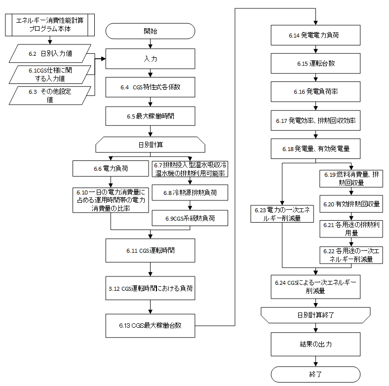
In order to create this calculation method, the cogeneration evaluation program CASCADEⅢ was developed to a method to calculate energy consumptions based on daily loading data, and parameters etc. used to evaluate actual work performance were added to this method.
A flow of evaluation is shown in the following diagram. The daily calculation results of power consumptions, heating and hot-water supply loads and other information are obtained from the main body of the energy consumption performance program. Based on these results, the operation status of a CGS is determined. In the main body of the program, the energy consumptions of electric power, cooling, heating and hot-water supply are calculated on the assumption that electric power or waste heat is not acquired from the CGS. In this program, the primary energy consumptions that can be reduced in the items of electric power, cooling, heating and hot-water supply, and the gas consumption of a CGS are calculated. Finally, the gas consumption of CGS is deducted from the energy consumptions of electric power, cooling, heating and hot-water supply that are calculated in the main body of the program, and then, the energy consumption of the whole building can be calculated in consideration of the increment of the gas consumption of CGS.
8.1.5 Input Value
8.1.5.1 Input value for CGS specifications
The list of set values for CSG and the absorption chiller/heater with auxiliary waste heat recovery that are inputted in the program are shown in the following table.
| Variable name | Description | Unit | Reference |
|---|---|---|---|
\(E_{cgs,rated}\) |
Rated generation output of CGS |
kW |
Form 7-3 |
\( N_{cgs} \) |
Number of installed CGSs |
Number |
Form 7-3 |
\(f_{cgs,e,rated}\) |
Rated power generation efficiency of CGS (Lower heating value standard) |
Non-dimensional |
Form 7-3 |
\(f_{cgs,e,75}\) |
Power generation efficiency of CGS at loading factor 0.75 (Lower heating value standard) |
Non-dimensional |
Form 7-3 |
\(f_{cgs,e,50}\) |
Power generation efficiency of CGS at loading factor 0.50 (Lower heating value standard) |
Non-dimensional |
Form 7-3 |
\(f_{cgs,hr,rated}\) |
Rated heat exhaust efficiency of CGS (Lower heating value standard) |
Non-dimensional |
Form 7-3 |
\(f_{cgs,hr,75}\) |
Heat exhaust efficiency of CGS at loading factor 0.75 (Lower heating value standard) |
Non-dimensional |
Form 7-3 |
\(f_{cgs,hr,50}\) |
Heat exhaust efficiency of CGS at loading factor 0.50 (Lower heating value standard) |
Non-dimensional |
Form 7-3 |
\(n_{pri,hr,c}\) |
Priority of waste heat use (cooling source) *1 |
Non-dimensional |
Form 7-3 |
\(n_{pri,hr,h}\) |
Priority of waste heat use (heat source) *1 |
Non-dimensional |
Form 7-3 |
\(n_{pri,hr,W}\) |
Priority of waste heat use (hot-water supply) *1 |
Non-dimensional |
Form 7-3 |
\( C_{24ope} \) |
Presence or absence of CSG 24-hour operation (Yes/NO) |
- |
Form 7-3 |
\(q_{AC,link,c,j,rated}\) |
Rated cooling capacity of absorption chiller/heater with auxiliary waste heat recovery |
kW/unit |
Form 7-3 |
\(E_{AC,link,c,j,rated}\) |
Rated consumption energy of a main module of an absorption chiller/heater with auxiliary waste heat recovery |
kW/unit |
Form 7-3 |
\(N_{AC,ref,link}\) |
Number of absorption chillers/heaters with auxiliary waste heat recovery in a system allowing for the use of waste heat of CGS |
Number |
Form 7-3 |
- Integer from 0 to 3 In the case where a column in the input sheet is blank, the value of an integer is assumed to be “0.” This means that waste heat is not used for the targeted purposes. One of \(n_{pri,hr,c}\), \(n_{pri,hr,h}\) and \(n_{pri,hr,W}\) must be “1.”
8.1.5.2 Input value by day (Read of results calculated for other systems)
Based on the results calculated for other systems, read the following values. The method for calculating these values is shown in Annex G.10
| Variable name | Description | Unit | Remarks |
|---|---|---|---|
\(E_{AC,total,d}\) |
Power consumption of air conditioning equipment at date |
MWh/day |
*1 |
\(E_{AC,ref,c,d}\) |
Primary energy consumption of a cooling source module of an absorption chiller/heater with auxiliary waste heat system recovery (system) allowing for the use of waste heat from CGS, at date d (total of primary energy consumptions of several cooling sources) |
MJ/day |
*2 |
\(mxL_{AC,ref,c,d}\) |
Loading factor of a cooling source of an absorption chiller/heater with auxiliary waste heat system recovery (system) allowing for the use of waste heat of CGS, at date d (Loading factors of several cooling sources are divided in proportion to their rated cooling capacities.) |
Non-dimensional |
*2 |
\(E_{AC,ref,h,hr,d}\) |
Primary energy consumption of a main module of a heat source group allowing for the use of waste heat of CGS, at date d (total of primary energy consumptions of several heat sources) |
MJ/day |
*2 |
\(q_{AC,ref,h,hr,d}\) |
Heating load of a heat source group allowing for the use of waste heat of CGS, at date d (total of heating loads of several heat source groups) |
MJ/day |
*2 |
\(E_{V,total,d}\) |
Power consumption of air conditioning system at date |
MWh/day |
*3 |
\(E_{L,total,d}\) |
Power consumption of lighting installation at date |
MWh/day |
*4 |
\(E_{W,total,d}\) |
Power consumption of hot-water supply system at date |
MWh/day |
*5 |
\(E_{W,hr,d}\) |
Primary energy consumption of a water heater (system) allowing for the use of waste heat of CGS, at date d (total of primary energy consumptions of water heaters) |
MJ/day |
*5 |
\(q_{W,hr,d}\) |
Supply load of a water heater (system) allowing for the use of waste heat of CGS, at date d (total of supply loads of several water heaters) |
MJ/day |
*5 |
\(E_{EV,total,d}\) |
Power consumption of hot-water supply system at date |
MWh/day |
*6 |
\(E_{PV,total,d}\) |
Power generation of system with effective use of energy (solar power generation system) at date |
MWh/day |
*7 |
\(E_{M,total,d}\) |
Power consumption of other system at date |
MWh/day |
*8 |
\(T_{AC,c,d}\) |
Operation time of an absorption chiller/heater with auxiliary waste heat system recovery (system) allowing for the use of waste heat of CGS, at date d (The largest among operation times of several cooing sources is employed.) |
h/day |
*2 |
\(T_{AC,h,d}\) |
Operation time of an heat source group allowing for the use of waste heat of CGS, at date d (The largest among operation times of several heat sources is employed.) |
h/day |
*2 |
\( f_{eopeHi} \) |
Average power ratio between operation and non-operation hours of building |
Non-dimensional |
*8 |
*1 Calculation result of air conditioning equipment Sum of power consumptions of a total heat exchanger, heat source main module, heat source auxiliary module, primary pump, cooling tower fan and cooling tower pump
*2 Calculation result of air conditioning equipment
*3 Calculation result of mechanical ventilation equipment
*4 Calculation result of lighting installation
*5 Calculation result of hot-water supply system
*6 Calculation result of elevator
*7 Calculation result of system with effective use of energy (solar power generation system)
*8 Calculation result of other system Value calculated from equipment heat generation in each room
8.1.6 Constant
The common constants that are used in this chapter is shown below.
| Variable name | Description | Unit | Value |
|---|---|---|---|
\( f_{eopeMn} \) |
Required power ratio for operation judgment standard |
Non-dimensional |
0.5 |
\( f_{hopeMn} \) |
Required waste heat ratio for operation judgment standard |
Non-dimensional |
0.5 |
\(f_{esub,cgswc}\) |
CGS’s auxiliary power ratio (in the presence of a cooling tower) |
Non-dimensional |
0.06 |
\(f_{esub,cgsac}\) |
CGS’s auxiliary power ratio (in the absence of a cooling tower) |
Non-dimensional |
0.05 |
\( f_{lh} \) |
Ratio of lower to higher heating value of gas |
Non-dimensional |
0.90222 |
\(f_{prime,e}\) |
Primary energy conversion coefficient of electricity |
MJ/kWh |
9.76 |
\(f_{COP,link,hr}\) |
COP at use of waste heat from absorption chiller/heater with auxiliary waste heat recovery |
Non-dimensional |
0.75 |
\( f_{elmax} \) |
Maximum share rate of power load of CGS |
Non-dimensional |
0.95 |
\( T_{STn} \) |
Maximum operation time of CGS |
h/day |
14 |
\(T_{STmin,W}\) |
Minimum operation time of CGS when waste heat is used only for hot-water supply |
h/day |
10 |
\(f_{cgs,e,cor}\) |
Correction of generation efficiency |
Non-dimensional |
0.99 |
\(f_{hr,loss}\) |
Heat loss rate of waste heat |
Non-dimensional |
0.97 |
8.2 Calculation of CGS Energy Consumption Characteristic
Determine each different coefficient to calculate a CGS’s energy consumption characteristic from power generation and heat exhaust efficiency inputs.
| Variable name | Description | Unit | Reference |
|---|---|---|---|
\(f_{ cgs, e, rated }\) |
Rated power generation efficiency of CGS (Lower heating value standard) |
- |
Form 7-3: ④ Power generation efficiency at loading factor 1.00 |
\(f_{ cgs, e, 75 }\) |
Power generation efficiency of CGS at loading factor 0.75 (Lower heating value standard) |
- |
Form 7-3: ⑤ Power generation efficiency at loading factor 0.75 |
\(f_{ cgs, e, 50 }\) |
Power generation efficiency of CGS at loading factor 0.5 (Lower heating value standard) |
- |
Form 7-3: ⑥ Power generation efficiency at loading factor 0.50 |
\(f_{ cgs, hr, rated }\) |
Rated heat exhaust efficiency of CGS (Lower heating value standard) |
- |
Form 7-3: ⑦ Heat exhaust efficiency at loading factor 1.00 |
\(f_{ cgs, hr, 75 }\) |
Heat exhaust efficiency of CGS at loading factor 0.75 (Lower heating value standard) |
- |
Form 7-3: ⑧ Heat exhaust efficiency at loading factor 0.75 |
\(f_{ cgs, hr, 50 }\) |
Heat exhaust efficiency of CGS at loading factor 0.5 (Lower heating value standard) |
- |
Form 7-3: ⑨ Heat exhaust efficiency at loading factor 0.50 |
| Variable name | Description | Unit | References |
|---|---|---|---|
\(f_{ e2 }\) |
Coefficient and term of quadratic formula of CGS’s power generation efficiency characteristic expression |
- |
8.15 |
\(f_{ e1 }\) |
Coefficient and term of linear formula of CGS’s power generation efficiency characteristic expression |
- |
8.15 |
\(f_{ e0 }\) |
Coefficient and term of CGS’s power generation efficiency characteristic expression |
- |
8.15 |
\(f_{ hr2 }\) |
Coefficient and term of quadratic formula of CGS’s heat exhaust efficiency characteristic expression |
- |
8.15 |
\(f_{ hr1 }\) |
Coefficient and term of linear formula of CGS’s heat exhaust efficiency characteristic expression |
- |
8.15 |
\(f_{ hr0 }\) |
Constant and term of CGS’s heat exhaust efficiency characteristic expression |
- |
8.15 |
Determine \(f_{ e2 }\) ,\(f_{ e1 }\) ,\(f_{ e0 }\) ,\(f_{ hr2 }\) ,\(f_{ hr1 }\) and \(f_{ hr0 }\) from the following formula, using the Lagrange interpolation formula.
8.3 Maximum Operation Time
Calculate a maximum operation time of a CGS.
| Variable name | Description | Unit | Reference |
|---|---|---|---|
\(C_{ 24ope }\) |
Presence or absence of CGS 24-hour operation (Yes/NO) |
- |
Form 7-3: ⑬ Presence or absence of 24-hour operation |
\(T_{ STn }\) |
Maximum operation time of CGS in the case of intermittent operation. |
h/day |
G.4 |
| Variable name | Description | Unit | References |
|---|---|---|---|
\(T_{ ST }\) |
Maximum operation time of CGS |
h/day |
8.7、8.8、8.9、8.10 |
A maximum operation time of CGS, \(T_{ ST }\), is assumed to be \(T_{ STn }\) regardless of building uses. In the presence of \(C_{ 24ope }\), however, the maximum operation time is assumed to be 24.
8.4 Power Loads
Calculate power loads.
| Variable name | Description | Unit | Reference |
|---|---|---|---|
\(E_{ AC, total, d }\) |
Power consumption of air conditioning equipment at date |
MWh/day |
8.1.5.2 |
\(E_{ V, total, d }\) |
Power consumption of air conditioning system at date |
MWh/day |
8.1.5.2 |
\(E_{ L, total, d }\) |
Power consumption of lighting installation at date |
MWh/day |
8.1.5.2 |
\(E_{ W, total, d }\) |
Power consumption of hot-water supply system at date |
MWh/day |
8.1.5.2 |
\(E_{ EV, total, d }\) |
Power consumption of hot-water supply system at date |
MWh/day |
8.1.5.2 |
\(E_{ M, total, d }\) |
Power consumption of other system at date |
MWh/day |
8.1.5.2 |
\(E_{ PV, total, d }\) |
Power generation of system with effective use of energy (solar power generation system) at date |
MWh/day |
8.1.5.2 |
| Variable name | Description | Unit | References |
|---|---|---|---|
\(E_{ e, total, d }\) |
Power consumption of building at date |
kWh/day |
8.9、8.10 |
8.5 Availability Rate of Waste Heat of Absorption Chiller/Heater with Auxiliary Waste Heat recovery
Calculate an availability rate of waste heat of an absorption chiller/heater with auxiliary waste heat recovery.
| Variable name | Description | Unit | Reference |
|---|---|---|---|
\(mxL_{ AC, ref, c, d }\) |
Load factor of a cooling source of an absorption chiller/heater with auxiliary waste heat system recovery (system) allowing for the use of waste heat of CGS, at date |
- |
8.1.5.2 |
\(f_{ link, rated, b }\) |
Availability rate of waste heat of absorption chiller/heater with auxiliary waste heat system recovery during its rated operation |
- |
G.8 |
\(f_{ link, min, b }\) |
Maximum loading factor at which a waste heat of absorption chiller/heater with auxiliary waste heat system recovery can operate only by waste heat |
- |
G.8 |
\(f_{ link, down }\) |
Rate of reduction of available waste heat by waste heat temperature |
- |
G.9 |
| Variable name | Description | Unit | References |
|---|---|---|---|
\(f_{ link, d }\) |
Availability rate of waste heat of absorption chiller/heater with auxiliary waste heat recovery at date |
- |
8.6 |
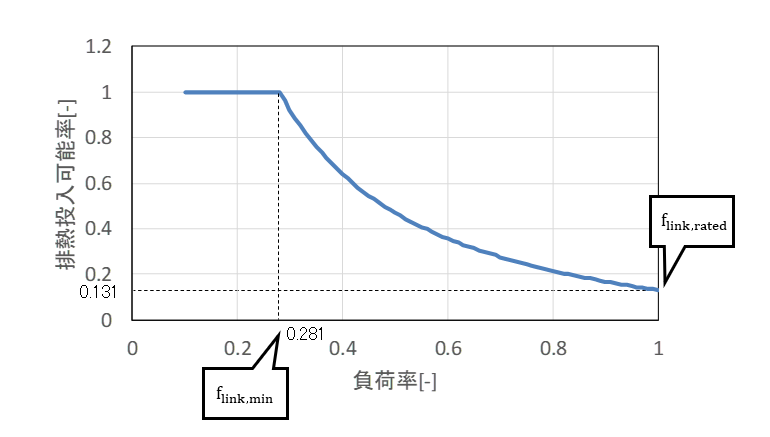
After determining a rate of available waste heat during rated operation of an absorption chiller/heater with auxiliary waste heat system recovery in consideration of a decline of the relevant rate that is caused by a temperature of heat exhaust, \(f_{ link, rated }\), and a maximum load factor of the absorption chiller/heater when it can operate with the use of only waste heat, \(f_{ link, min }\), calculate a rate of available waste heat for the absorption chiller/heater, \(f_{ link, d }\).
Rate of available waste heat for absorption chiller/heater with auxiliary waste heat recovery
The rate of available waste heat for an absorption chiller/heater with auxiliary waste heat recovery represents an amount of energy that can be replaced with waste heat, of input energy required for production of a cooling source in each operation load factor. The rate of available waste heat for the absorption chiller/heater with auxiliary waste heat recovery according to each load factor is shown in the following figure. The absorption chiller/heater can produce cooling sources with the use of only waste heat in the range of low loads, but in the range of high loads, it becomes necessary to charge gas etc. into the machine due to the reduction of the relevant rate.
8.6 Heat Exhaust Load of Cooling Source
Calculate a heat exhaust load of a cooling source.
| Variable name | Description | Unit | Reference |
|---|---|---|---|
\(E_{ AC, ref, c, d }\) |
Primary energy consumption of a cooling source main module of an absorption chiller/heater with auxiliary waste heat system recovery (system) allowing for the use of waste heat of CGS, at date |
MJ/day |
8.1.5.2 |
\(f_{ link, d }\) |
Availability rate of waste heat of absorption chiller/heater with auxiliary waste heat recovery at date |
- |
8.5 |
\(q_{ AC, link, c, j, rated }\) |
Rated cooling capacity of absorption chiller/heater with auxiliary waste heat recovery |
kW/unit |
Form 2-5: ⑩ Rated cooling capacity |
\(E_{ AC, link, c, j, rated }\) |
Rated consumption energy of a main module of an absorption chiller/heater with auxiliary waste heat recovery |
kW/unit |
Form 2-5: ⑪ Rated energy consumption of main module |
\(N_{ AC, ref, link }\) |
Number of absorption chillers/heaters with auxiliary waste heat recovery in a system allowing for the use of waste heat of CGS |
Number |
Form 2-5: ⑧ Number of devices |
\(n_{ pri, hr, c }\) |
Priority of waste heat use (cooling source) |
- |
Form 7-3: ⑩ Priority of waste heat use, air conditioning cooling source |
\(f_{ COP, link, hr }\) |
COP at use of waste heat from absorption chiller/heater with auxiliary waste heat recovery |
- |
G.5 |
\(n_{ pri, hr, c}\) |
Priority of waste heat use (cooling source) |
Non-dimensional |
Form 7-3 |
| Variable name | Description | Unit | References |
|---|---|---|---|
\(q_{ AC, ref, ch, hr, d }\) |
Heat exhaust load of an absorption chiller/heater with auxiliary waste heat system recovery (system) allowing for the use of waste heat of CGS, at date |
MJ/day |
8.7、8.10 |
\(E_{ AC, ref, c, hr, d }\) |
In the use of waste heat, possible amount of reduction of primary energy consumption of a cooling source main module of an absorption chiller/heater with auxiliary waste heat system recovery (system) allowing for the use of waste heat of CGS, at date |
MJ/day |
8.10 |
(Supplementary document) Detailed manual of formula for cooling source’s heat exhaust load
8.7 Heat Loads of CGS Systems
Calculate heat loads of CGS systems.
| Variable name | Description | Unit | Reference |
|---|---|---|---|
\(q_{ AC, ref, c, hr, d }\) |
Heat exhaust load of an absorption chiller/heater with auxiliary waste heat system recovery (system) allowing for the use of waste heat of CGS, at date |
MJ/day |
8.6 |
\(q_{ AC, ref, h, hr, d }\) |
Heating load of a heat source group allowing for the use of waste heat of CGS, at date |
MJ/day |
8.1.5.2 |
\(q_{ W, hr, d }\) |
Supply load of a water heater (system) allowing for the use of waste heat of CGS, at date |
MJ/day |
5.6 |
\(T_{ AC, c, d }\) |
Operation time of an absorption chiller/heater with auxiliary waste heat system recovery (system) allowing for the use of waste heat of CGS, at date |
h/day |
8.1.5.2 |
\(T_{ AC, h, d }\) |
Operation time of a heat source group allowing for the use of waste heat of CGS, at date |
h/day |
8.1.5.2 |
\(T_{ ST }\) |
Maximum operation time of CGS |
h/day |
8.3 |
| Variable name | Description | Unit | References |
|---|---|---|---|
\(q_{ hr, AC, c, d }\) |
Heat exhaust load of an absorption chiller/heater with auxiliary waste heat system recovery (system) allowing for the use of waste heat of CGS, at date |
MJ/day |
- |
\(q_{ hr, AC, h, d }\) |
Heat exhaust load of a heat source group allowing for the use of waste heat of CGS, at date |
MJ/day |
- |
\(q_{ hr, total, d }\) |
Heat load of CGS heat exhaust system at date |
MJ/day |
8.9、8.11 |
In order to determine a heat load of a CGS heat exhaust system at a date d, \(q_{ hr, total, d }\), heat exhaust loads of cooling and heating sources are determined, and a heat exhaust load of hot-water supply is added to the determined loads. The heat exhaust load of the cooling source is corrected according to the number of hours as indicated below if a daily cooling time of the source is shorter than the maximum operation time of a CGS.
The heat exhaust load of the heating source is corrected in the same way as that of the cooling source.
Finally, a hot-water supply load is added to the heat exhaust load of the cooling and heating sources. The sum of the supply load and the exhaust load is a heat load of the CGS heat exhaust system. For reference, it is possible to use the exhaust heat of a CGS for hot-water supply by installing a hot water tank even if generation hours of hot-water supply load are different from operation hours of the CGS. For this reason, the relevant load is not corrected based the operation hours.
8.8 Ratio between Power Consumption during Operation Hours and Daily Power Consumption
Calculate a ratio between a power consumption during operation hours and daily power consumption.
| Variable name | Description | Unit | Reference |
|---|---|---|---|
\(T_{ ST }\) |
Maximum operation time of CGS |
h/day |
8.3 |
\(f_{ eopeHi }\) |
Average power ratio between operation and non-operation hours of building |
- |
8.1.5.2 |
| Variable name | Description | Unit | References |
|---|---|---|---|
\(f_{ eope, R }\) |
Ratio between power consumption during operation hours and daily power consumption |
- |
- |
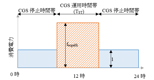
The above formula is a formula from which a power consumption of a CGS during its operation hours (area of orange part) is determined in comparison with a total of power consumptions in one day as shown in the following figure (total of areas of light blue and orange parts). \(f_{ eopeHi }\) represents an average power consumption of a CGS during its operation hours on the assumption that an average power consumption of the CGS during its non-operation hours is 1. The power consumption of the CGS during its operation hours (area of orange part) is represented as \(f_{ eopeHi } \times T_{ ST }\) while the power consumption of the CGS during its non-operation hours (area of light blue part) is represented as \( (24 - T_{ST}) \times 1 \). Accordingly, the above formula can be obtained.
8.9 Operation Time of CGS
Calculate an operation time of CGS.
| Variable name | Description | Unit | Reference |
|---|---|---|---|
\(E_{ e, total, d }\) |
Power consumption of building at date |
kWh/day |
8.4 |
\(q_{ hr, total, d }\) |
Heat load of CGS heat exhaust system at date |
MJ/day |
8.7 |
\(E_{ cgs, rated }\) |
Rated generation output of CGS |
kW |
8.1.5.1 |
\(f_{ cgs, e, rated }\) |
Rated power generation efficiency of CGS (Lower heating value standard) |
- |
8.1.5.1 |
\(f_{ cgs, hr, rated }\) |
Rated heat exhaust efficiency of CGS (Lower heating value standard) |
- |
8.1.5.1 |
\(f_{ eopeMn }\) |
Required power ratio for operation judgment standard |
- |
8.1.6 |
\(f_{ hopeMn }\) |
Required waste heat ratio for operation judgment standard |
- |
8.1.6 |
\(f_{ esub, cgswc }\) |
CGS’s auxiliary power ratio (in the presence of a cooling tower) |
- |
8.1.6 |
\(f_{ esub, cgsac }\) |
CGS’s auxiliary power ratio (in the absence of a cooling tower) |
- |
8.1.6 |
\(T_{ AC, c, d }\) |
Operation time of an absorption chiller/heater with auxiliary waste heat system recovery (system) allowing for the use of waste heat of CGS, at date |
h/day |
8.1.5.2 |
\(T_{ AC, h, d }\) |
Operation time of a heat source group allowing for the use of waste heat of CGS, at date |
h/day |
8.1.5.2 |
\(T_{ ST }\) |
Maximum operation time of CGS |
h/day |
8.3 |
\(T_{ STmin, W }\) |
Minimum operation time of CGS when waste heat is used only for hot-water supply |
h/day |
8.1.6 |
\(f_{ eope, R }\) |
Ratio between power consumption during operation hours and daily power consumption |
- |
8.8 |
\(N_{ pri, hr, c }\) |
Priority of waste heat use (cooling source) |
Number |
8.1.5.1 |
\(N_{ pri, hr, h }\) |
Priority of waste heat use (heating source) |
Number |
8.1.5.1 |
| Variable name | Description | Unit | References |
|---|---|---|---|
\(T_{ cgs, d }\) |
Operation time of CGS at date |
h/day |
8.10 |
\(f_{ esub, cgs }\) |
Power ratio of CGS auxiliary module |
- |
8.12 |
A CGS’s auxiliary power ratio, \(f_{ esub, cgs }\), is determined as shown below according to a rated power generation output of the CGS. This ratio is based on that a micro gas engine with a rated power generation output of 50kW or less does not have a cooling tower, and accordingly, its auxiliary power is low.
An operation time of CGS at a date d, \(T_{ cgs, d }\), is determined form the following formula.
(1) \( n_{pri,hr,c} = 0 \land n_{pri,hr,h} = 0 \)
- a) In the case of \(\tfrac{q_{hr,total,d}}{E_{cgs,rated} \times 3.6 \times f_{hopeMn}}\times \tfrac{f_{cgs,e,rated}}{f_{cgs,h,rated}} \geqq T_{ST}\land \tfrac{E_{e,total,d} \times f_{eope,R} \times (1 + f_{esub,cgs})}{E_{cgs,rated} \times f_{eopMn}} \geqq T_{ST} \)
- b) Not falling under (a), \( \left( \tfrac{q_{hr,total,d}}{E_{cgs,rated} \times 3.6 \times f_{hopeMn}} \times \tfrac{f_{cgs,e,rated}}{f_{cgs,h,rated}} \geqq T_{STmin,W} \land \tfrac{E_{e,total,d} \times f_{eope,R} \times (1 + f_{esub,cgs})}{E_{cgs,rated} \times f_{eopMn}} \geqq T_{STmin,W} \right) = \text{True} \)
- c) Not falling under a) or b)
(2) Not falling under (1), \(T_{ AC, c, d } \geqq T_{ AC, h, d }\)
- a) In the case of \( \dfrac{q_{hr,total,d}}{E_{cgs,rated} \times 3.6 \times f_{hopeMn}} \times \dfrac{f_{cgs,e,rated}}{f_{cgs,h,rated}} \geqq T_{ST} \land \dfrac{ E_{e,total,d} \times f_{eope,R} \times (1 + f_{esub,cgs}) }{ E_{cgs,rated} \times f_{eopMn} } \geqq T_{ST} \)
- b) Not falling under (a), \( \dfrac{q_{hr,total,d}}{E_{cgs,rated} \times 3.6 \times f_{hopeMn}} \times \dfrac{f_{cgs,e,rated}}{f_{cgs,h,rated}} \geqq T_{AC,c,d} \land \dfrac{ E_{e,total,d} \times f_{eope,R} \times (1 + f_{esub,cgs}) }{ E_{cgs,rated} \times f_{eopMn} } \geqq T_{AC,c,d} = \text{True} \)
- c) Not falling under a) or b)
(3) Not falling under (1), \(T_{ AC, c, d } < T_{ AC, h, d }\)
- a) In the case of \( \dfrac{q_{hr,total,d}}{E_{cgs,rated} \times 3.6 \times f_{hopeMn}} \times \dfrac{f_{cgs,e,rated}}{f_{cgs,h,rated}} \geqq T_{ST} \land \dfrac{ E_{e,total,d} \times f_{eope,R} \times (1 + f_{esub,cgs}) }{ E_{cgs,rated} \times f_{eopMn} } \geqq T_{ST} \)
- b) Not falling under (a), \( \dfrac{q_{hr,total,d}}{E_{cgs,rated} \times 3.6 \times f_{hopeMn}} \times \dfrac{f_{cgs,e,rated}}{f_{cgs,h,rated}} \geqq T_{AC,c,d} \land \dfrac{ E_{e,total,d} \times f_{eope,R} \times (1 + f_{esub,cgs}) }{ E_{cgs,rated} \times f_{eopMn} } \geqq T_{AC,c,d} = \text{True} \)
- c) Not falling under a) or b)
(1) is the case where “waste heat is used only for hot-water supply.” In this case, \(T_{ STmin, W }\) (=10 hours) is assumed to a minimum operation time.
1) and (3) are the case in which waste heat is used for cooling or heating. In this case, CGS’s operation time is assumed to be its maximum operation time by reference to the longer of cooling and heating operations if there are sufficient power and heat loads.
\(\frac{ q_{ hr, total, d } }{ E_{ cgs, rated } \times 3.6 \times f_{ hopeMn } } \times \frac{ f_{ cgs, e, rated } }{ f_{ cgs, h, rated } }\) in the conditional expression represents hours of operation time in the case where a heat load of the CGS heat exhaust system is divided by an amount of heat exhaust applicable to the required waste heat ratio for operation judgment standard. Similarly, \(\frac{ E_{ e, total, d } \times f_{ eope, R } \times ( 1 + f_{ esub, cgs } ) }{ E_{ cgs, rated } \times f_{ eopMn } }\) represents hours of operation time in the case where power is generated in the condition applicable to the required power ratio for operation judgment standard. If both of these hours exceed a maximum operation time \(T_{ ST }\), the maximum operation time is assumed to be an operation time of CGS at that day, deeming the sufficiency of the loads, Even in the case where this does not apply, if both of them exceed a cooling or heating operation time (the heating operation time is used if being longer than the cooling operation time), or a “minimum operation time (10 hours) of a CGS in the case where waste heat is used only for hot-water supply,” the relevant time (cooling operation time, heating operation time or minimum operation time) is assumed to be an operation time of the CGS at that day. If they do not meet the above time requirements, the CGS shall not be operated at that day.
(Supplementary document) Detailed manual of formula for conditional expression
8.10 Loads during CGS’s Operation Time
Calculate a load during an operation time of a CGS.
| Variable name | Description | Unit | Reference |
|---|---|---|---|
\(E_{ e, total, d }\) |
Power consumption of building at date |
kWh/day |
8.4 |
\(E_{ AC, ref, c, hr, d }\) |
In the use of waste heat, possible amount of reduction of primary energy consumption of a cooling source main module of an absorption chiller/heater with auxiliary waste heat system recovery (system) allowing for the use of waste heat of CGS, at date |
MJ/day |
8.6 |
\(q_{ AC, ref, c, hr, d }\) |
Heat exhaust load of an absorption chiller/heater with auxiliary waste heat system recovery (system) allowing for the use of waste heat of CGS, at date |
MJ/day |
8.6 |
\(E_{ AC, ref, h, hr, d }\) |
In the use of waste heat, possible amount of reduction of primary energy consumption of a main module of a heat source group allowing for the use of waste heat of CGS, at date |
MJ/day |
8.1.5.2 |
\(q_{ AC, ref, h, hr, d }\) |
Heat exhaust load of a heat source group allowing for the use of waste heat of CGS, at date |
MJ/day |
8.1.5.2 |
\(E_{ W, hr, d }\) |
In the use of waste heat, possible amount of reduction of primary energy consumption of a main module of a water heater (system) allowing for the use of waste heat of CGS, at date |
MJ/day |
8.1.5.2 |
\(q_{ W, hr, d }\) |
Heat exhaust load of a water heater (system) allowing for the use of waste heat of CGS, at date |
MJ/day |
8.1.5.2 |
\(T_{ ST }\) |
Maximum operation time of CGS |
h/day |
8.3 |
\(T_{ AC, c, d }\) |
Operation time of an absorption chiller/heater with auxiliary waste heat system recovery (system) allowing for the use of waste heat of CGS, at date |
h/day |
8.1.5.2 |
\(T_{ AC, h, d }\) |
Operation time of a heat source group allowing for the use of waste heat of CGS, at date |
h/day |
8.1.5.2 |
\(f_{ eope, R }\) |
Ratio between power consumption during operation hours and daily power consumption |
- |
8.8 |
\(T_{ cgs, d }\) |
Operation time of CGS at date |
h/day |
8.9 |
| Variable name | Description | Unit | References |
|---|---|---|---|
\(E_{ e, total, on, d }\) |
Power consumption of building during CGS operation hours at date |
kWh/day |
- |
\(E_{ AC, ref, c, hr, on, d }\) |
In the use of waste heat, possible amount of reduction of primary energy consumption of a cooling source main module of an absorption chiller/heater with auxiliary waste heat system recovery (system) allowing for the use of waste heat of CGS during its operation, at date |
MJ/day |
- |
\(q_{ AC, ref, c, hr, on, d }\) |
Available waste heat for a cooling source of absorption chiller/heater with auxiliary waste heat system recovery (system) allowing for the use of waste heat of CGS during its operation, at date |
MJ/day |
- |
\(E_{ AC, ref, h, hr, on, d }\) |
Primary energy consumption of a main module of a heat source group allowing for the use of waste heat of CGS during its operation, at date |
MJ/day |
- |
\(q_{ AC, ref, h, hr, on, d }\) |
Available waste heat for a heat source group allowing for the use of waste heat of CGS during its operation, at date |
MJ/day |
- |
\(E_{ W, hr, on, d }\) |
Primary energy consumption of a water heater (system) allowing for the use of waste heat of CGS, at date |
MJ/day |
- |
\(q_{ AC, ref, h, hr, on, d }\) |
Available waste heat for a water heater (system) allowing for the use of waste heat of CGS during its operation, at date |
MJ/day |
- |
\(q_{ total, hr, on, d }\) |
Total of available waste heat during CSG operation at date |
MJ/day |
- |
Correct a power consumption of a building during the operation hours of a CGS by its operation time in the following formula.
Available waste heat for hot-water supply and a primary energy consumption of a water heater (system) allowing for the use of waste heat during the operation hours of the CGS are not corrected by its operation time, based on that loads during non-operation hours of the CGS can be also treated by installing a tank.
During the operation hours of a CGS, available waste heat for a cooling source, and primary energy of a main module is consumed. A possible amount of reduction in the relevant amount and the primary energy consumption is determined from the following formula. If the cooling operation time is shorter than the operation time of a CGS, the relevant energy consumption is not corrected by the operation time of the CGS. If the cooling operation time is longer than the operation time of the CGS, available waste heat for the cooling source during the operation hours of the CGS is determined in proportion to the number of hours.
Similarly, available waste heat for a heating source , and a primary energy consumption of a main module of a heat source group allowing for the use of waste heat, during the operation hours of the CGS, are determined from the following formula.
A total of available waste heat amounts during the operation time of a CGS at a date d is determined from the following formula based on the value calculated in the above formula.
8.11 Maximum Number of Operating CGSs
Calculate the maximum number of operating CGSs.
| Variable name | Description | Unit | Reference |
|---|---|---|---|
\(q_{ hr, total, d }\) |
Heat load of CGS heat exhaust system at date |
MJ/day |
8.7 |
\(E_{ cgs, rated }\) |
Rated generation output of CGS |
kW |
8.x |
\(f_{ cgs, e, rated }\) |
Rated power generation efficiency of CGS (Lower heating value standard) |
- |
8.1.5.1 |
\(f_{ cgs, hr, rated }\) |
Rated heat exhaust efficiency of CGS (Lower heating value standard) |
- |
8.1.5.1 |
\(T_{ cgs, d }\) |
Operation time of CGS at date |
h/day |
8.9 |
\(N_{ cgs }\) |
Number of installed CGSs |
Number |
8.x |
| Variable name | Description | Unit | References |
|---|---|---|---|
\(N'_{ cgs, on, max, d }\) |
Temporary maximum number of operating CGSs at date |
Number |
- |
\(N_{ cgs, on, max, d }\) |
Maximum number of operating CGSs at date |
Number |
- |
The maximum number of operating CGSs at a date d, \(N'_{ cgs, on, max, d }\), is determined form the following formula.
In the case where \(\left \lceil{ x }\right \rceil\) is a function of Ceil and x contains decimals, it is rounded to an integer.
Based on the comparison between the number of installed CGSs and the determined temporary maximum number of operating CGSs, the maximum number of the CGSs is determined.
8.12 Power Generation Loads
Calculate power generation loads.
| Variable name | Description | Unit | Reference |
|---|---|---|---|
\(E_{ e, total, on, d }\) |
Power consumption of building during CGS operation hours at date |
kWh/day |
8.10 |
\(f_{ esub, cgs }\) |
CGS’s auxiliary power ratio |
- |
8.9 |
\(f_{ elmax }\) |
Maximum share rate of power load of CGS |
- |
8.1.6 |
| Variable name | Description | Unit | References |
|---|---|---|---|
\(E_{ e, load, d }\) |
Power generation load of CGS at date |
kWh/day |
- |
8.13 Number of Operating CGSs
Calculate the number of operating CGSs.
| Variable name | Description | Unit | Reference |
|---|---|---|---|
\(E_{ e, load, d }\) |
Power generation load of CGS at date |
kWh/day |
8.12 |
\(E_{ cgs, rated }\) |
Rated generation output of CGS |
kW |
8.x |
\(N_{ cgs, on, max, d }\) |
Maximum number of operating CGSs at date |
Number |
8.11 |
\(T_{ cgs, d }\) |
Operation time of CGS at date |
h/day |
8.9 |
| Variable name | Description | Unit | References |
|---|---|---|---|
\(N'_{ cgs, on, d }\) |
Temporary value of operating CGSs at date |
Number |
- |
\(N_{ cgs, on, d }\) |
Number of operating CGSs at date |
Number |
- |
In the case where \(\left \lceil{ x }\right \rceil\) is a function of Ceil and x contains decimals, it is rounded to an integer.
8.14 Load Factor of Power Generation
Calculate a load factor of power generation.
| Variable name | Description | Unit | Reference |
|---|---|---|---|
\(E_{ e, load, d }\) |
Power generation load of CGS at date |
kWh/day |
8.12 |
\(E_{ cgs, rated }\) |
Rated generation output of CGS |
kW |
8.1.5.1 |
\(N_{ cgs, on, d }\) |
Number of operating CGSs at date |
Number |
8.13 |
\(T_{ cgs, d }\) |
Operation time of CGS at date |
h/day |
8.9 |
| Variable name | Description | Unit | References |
|---|---|---|---|
\(mxL_{ cgs, d }\) |
Load factor of CGS at date |
- |
8.1.15 |
8.15 Power Generation and Waste Heat Recovery Efficiencies
Calculate power generation and waste heat recovery efficiencies.
| Variable name | Description | Unit | Reference |
|---|---|---|---|
\(f_{ e2 }\) |
Coefficient and term of quadratic formula of CGS’s power generation efficiency characteristic expression |
- |
8.2 |
\(f_{ e1 }\) |
Coefficient and term of linear formula of CGS’s power generation efficiency characteristic expression |
- |
8.2 |
\(f_{ e0 }\) |
Coefficient and term of CGS’s power generation efficiency characteristic expression |
- |
8.2 |
\(f_{ hr2 }\) |
Coefficient and term of quadratic formula of CGS’s heat exhaust efficiency characteristic expression |
- |
8.2 |
\(f_{ hr1 }\) |
Coefficient and term of linear formula of CGS’s heat exhaust efficiency characteristic expression |
- |
8.2 |
\(f_{ hr0 }\) |
Constant and term of CGS’s heat exhaust efficiency characteristic expression |
- |
8.2 |
\(mxL_{ cgs, d }\) |
Load factor of CGS at date |
- |
8.14 |
| Variable name | Description | Unit | References |
|---|---|---|---|
\(mxR_{ e, cgs, d }\) |
Power generation efficiency of CGS at date d (Lower heating value standard) |
- |
8.17 |
\(mxR_{ hr, cgs, d }\) |
Recovery efficiency of waste heat from CGS at date d (Lower heating value standard) |
- |
8.17 |
Determine a power generation efficiency (lower heating value standard) of a model group I, \(mxR_{ e, cgs, d }\), and a waste heat recovery efficiency of the group (lower heating value standard), at a date d, from the following formula.
8.16 Power Generation and Effective Power Generation
Calculate a power generation and effective power generation.
| Variable name | Description | Unit | Reference |
|---|---|---|---|
\(E_{ cgs, rated }\) |
Rated power generation of CSG at date |
kW |
8.1.5 |
\(N_{ cgs, on, d }\) |
Number of operating CGSs at date |
Number |
8.13 |
\(T_{ cgs, d }\) |
Operation time of CGS at date |
h/day |
8.11 |
\(mxL_{ cgs, d }\) |
Load factor of CGS at date |
- |
8.14 |
\(f_{ esub, cgs }\) |
CGS’s auxiliary power ratio |
- |
8.9 |
| Variable name | Description | Unit | References |
|---|---|---|---|
\(E_{ e, cgs, d }\) |
Power generation of CGS at date |
kWh/day |
- |
\(E_{ ee, cgs, d }\) |
Effective power generation of CGS at date |
kWh/day |
- |
8.17 Fuel Consumption and Waste Heat Recovery
Calculate a fuel consumption and waste heat recovery.
| Variable name | Description | Unit | Reference |
|---|---|---|---|
\(E_{ e, cgs, d }\) |
Power generation of CGS at date |
kWh/day |
8.16 |
\(mxR_{ e, cgs, d }\) |
Power generation efficiency of CGS at date d (Lower heating value standard) |
- |
8.15 |
\(mxR_{ hr, cgs, d }\) |
Waste efficiency of heat recovery from CGS at date d (Lower heating value standard) |
- |
8.15 |
\(f_{ lh }\) |
Ratio of lower to higher heating value of gas |
- |
8.1.6 |
\(f_{ cgs, e, cor }\) |
Correction of generation efficiency |
- |
8.1.6 |
| Variable name | Description | Unit | References |
|---|---|---|---|
\(E_{ s, cgs, d }\) |
Fuel consumption of CGS at date d (Higher heating value standard) |
MJ/day |
8.22 |
\(q_{ hr, cgs, d }\) |
Waste heat recovery from CGS at date |
MJ/day |
8.18 |
The fuel consumption of a CGS is multiplied by a power generation efficiency correction in the formula for waste heat recovery from the GCG, \(q_{ hr, cgs, d }\), because the effect given when the fuel consumption of the CGS (Higher heating value standard) \(E_{ s, cgs, d }\) is multiplied by \(f_{ cgs, e, cor }\) as a power generation efficiency correction value is cancelled out. This is due to that the power generation efficiency correction \(f_{ cgs, e, cor }\) is intended to increase the fuel consumption and not intended for resultant increase of the waste heat recovery.
8.18 Effective Waste Heat Recovery
Calculate an effective waste heat recovery.
| Variable name | Description | Unit | Reference |
|---|---|---|---|
\(q_{ hr, cgs, d }\) |
Waste heat recovery from CGS at date |
MJ/day |
8.17 |
\(q_{ total, hr, on, d }\) |
Total of available waste heat amounts during CGS operation at date |
MJ/day |
8.10 |
\(f_{ hr, loss }\) |
Heat loss rate of waste heat |
- |
8.1.6 |
| Variable name | Description | Unit | References |
|---|---|---|---|
\(q_{ ehr, cgs, d }\) |
Effective waste heat recovery at date |
MJ/day |
8.19 |
8.19 Waste Heat Usage in Each Use
Calculate a waste heat usage in each use.
| Variable name | Description | Unit | Reference |
|---|---|---|---|
\(q_{ ehr, cgs, d }\) |
Effective waste heat recovery amount at date |
MJ/day |
8.18 |
\(q_{ AC, ref, c, hr, on, d }\) |
Available waste heat for cooling source of absorption chiller/heater with auxiliary waste heat system recovery (system) allowing for the use of waste heat of CGS during its operation, at date |
MJ/day |
8.10 |
\(q_{ AC, ref, h, hr, on, d }\) |
Available waste heat for heat source group allowing for the use of waste heat during CGS operation time, at date |
MJ/day |
8.10 |
\(q_{ W, hr, on, d }\) |
Available waste heat for water heater (system) allowing for the use of waste heat during CGS operation time, at date |
MJ/day |
8.10 |
\(n_{ pri, hr, c }\) |
Priority of waste heat use (cooling source) |
- |
8.1.5.2 |
\(n_{ pri, hr, h }\) |
Priority of waste heat use (heating source) |
- |
8.1.5.2 |
\(n_{ pri, hr, W }\) |
Priority of waste heat use (hot-water supply) |
- |
8.1.5.2 |
| Variable name | Description | Unit | References |
|---|---|---|---|
\(q_{ AC, ref, c, ehr, d }\) |
Waste heat usage for a cooling source of an absorption chiller/heater with auxiliary waste heat system recovery (system), at date |
MJ/day |
8.20 |
\(q_{ AC, ref, h, ehr, d }\) |
Waste heat usage of heat source group at date |
MJ/day |
8.20 |
\(q_{ W, ehr, d }\) |
Waste heat usage of water heater (system) at date |
MJ/day |
8.20 |
\(q_{ pri1, ehr, d }\) |
Waste heat usage in use with priority order 1st at date |
MJ/day |
- |
\(q_{ pri2, ehr, d }\) |
Waste heat usage in use with priority order 2nd at date |
MJ/day |
- |
\(q_{ pri3, ehr, d }\) |
Waste heat usage in use with priority order 3rd at date |
MJ/day |
- |
\(q_{ pri1, ehr, on, d }\) |
Available waste heat in use with the priority order 1st at date |
MJ/day |
- |
\(q_{ pri2, ehr, on, d }\) |
Available waste heat in use with the priority order 2nd at date |
MJ/day |
- |
\(q_{ pri3, ehr, on, d }\) |
Available waste heat in use with the priority order 3rd at date |
MJ/day |
- |
Calculate a waste heat usage in each use at a date d according to the priority order of use of waste heat.
First, allocate an available waste heat to the use with the priority order 1st (one of cooling, heating or hot-waster supply) to \(q_{pri1,ehr,on,d}\), and also that with the priority order 2nd and 3rd according to the priority order of use of waste heat.
Next, if an effective waste heat recovery obtained from a CGS, \(q_{ ehr, cgs, d }\), is larger than an available waste heat with the priority order 1st, \(q_{ pri1, ehr, on, d }\) (in the case of the following (1)), calculate how much hot water is available to the use with the priority order 2nd, on the assumption that all of the available waste heat with the priority order 1st, \(q_{ pri1, ehr, on, d }\) can be supplied. In the same way, calculate it for the use with the priority order 3rd.
(1) In the case of \( q_{ehr,cgs,d} \geqq q_{pri1,ehr,on,d} \)
a) In the case of \( q_{ehr,cgs,d} - q_{pri1,ehr,d} \geqq q_{pri2,ehr,on,d} \)
i) In the case of \( q_{ehr,cgs,d} - q_{pri1,ehr,d} - q_{pri2,ehr,d} \geqq q_{pri3,ehr,on,d} \)
ii) In the case of \( q_{ehr,cgs,d} - q_{pri1,ehr,d} - q_{pri2,ehr,d} < q_{pri3,ehr,on,d} \)
ii) In the case of \( q_{ehr,cgs,d} - q_{pri1,ehr,d} < q_{pri2,ehr,on,d} \)
(2) In the case of \( q_{ehr,cgs,d} < q_{pri1,ehr,on,d} \)
Finally, after determining how much waste heat is available to the uses with the priority orders 1st. 2nd and 3rd in the above (1) or (2), allocate determined available waste heat to cooling, heating and hot-water supply.
8.20 Reduction of Primary Energy in Each Use
Calculate a reduction of primary energy in each use.
| Variable name | Description | Unit | Reference |
|---|---|---|---|
\(E_{ AC, ref, c, hr,on, d }\) |
In the use of waste heat, possible amounts of reduction in primary energy consumption of a cooling source main module of an absorption chiller/heater with auxiliary waste heat system recovery (system) allowing for the use of waste heat of CGS during its operation, at date |
MJ/day |
8.10 |
\(E_{ AC, ref, h, hr,on, d }\) |
Primary energy consumption of a main module of a heat source group allowing for the use of waste heat of CGS during its operation, at date |
MJ/day |
8.10 |
\(E_{ W, hr,on, d }\) |
Primary energy consumption of a water heater (system) allowing for the use of waste heat of CGS, at date |
MJ/day |
8.10 |
\(q_{ AC, ref, c, hr, on, d }\) |
Available waste heat for cooling source of absorption chiller/heater with auxiliary waste heat system recovery (system) allowing for the use of waste heat of CGS during its operation, at date |
MJ/day |
8.10 |
\(q_{ AC, ref, h, hr, on, d }\) |
Available waste heat for heat source group allowing for the use of waste heat during CGS operation time, at date |
MJ/day |
8.10 |
\(q_{ W, hr, on, d }\) |
Available waste heat for water heater (system) allowing for the use of waste heat during CGS operation time, at date |
MJ/day |
8.10 |
\(q_{ AC, ref, c, ehr, d }\) |
Waste heat usage for a cooling source of an absorption chiller/heater with auxiliary waste heat system recovery (system), at date |
MJ/day |
8.19 |
\(q_{ AC, ref, h, ehr, d }\) |
Waste heat usage of heat source group at date |
MJ/day |
8.19 |
\(q_{ W, hr, on, d }\) |
Waste heat usage of water heater (system) at date |
MJ/day |
8.19 |
| Variable name | Description | Unit | References |
|---|---|---|---|
\(E_{ AC, ref, c, red, d }\) |
Reduction of primary energy of cooling at date |
MJ/day |
8.22 |
\(E_{ AC, ref, h, red, d }\) |
Reduction of primary energy of heating at date |
MJ/day |
8.22 |
\(E_{ W, red, d }\) |
Reduction of primary energy of hot-water supply at date |
MJ/day |
8.22 |
A reduction of primary energy of cooling at a date d, \(E_{ AC, ref, c, red, d }\), is determined from the following formula.
A reduction of primary energy of heating at a date d, \(E_{ AC, ref, h, red, d }\), is determined from the following formula.
A reduction of primary energy of heating at a date d, \(E_{ W, red, d }\), is determined from the following formula.
These formulas are based on the concept that a primary energy consumption of waste heat utilization equipment (a heater, an air conditioner or a water heater) is reduced according to a ratio between available waste heat and actually used waste heat.
8.21 Reduction of Primary Energy of Electric Power
Calculate a reduction of primary energy of electric power.
| Variable name | Description | Unit | Reference |
|---|---|---|---|
\(E_{ ee, cgs, d }\) |
Effective power generation of CGS at date |
kWh/day |
8.16 |
| Variable name | Description | Unit | References |
|---|---|---|---|
\(E_{ e, red, d }\) |
Reduction of primary energy of power generation at date |
MJ/day |
8.22 |
8.22 Reduction of Primary Energy of CGS
Calculate a reduction of primary energy of a CGS.
| Variable name | Description | Unit | Reference |
|---|---|---|---|
\(E_{ s, cgs }\) |
Fuel consumption of CGS at date d (Higher heating value standard) |
MJ/day |
8.17 |
\(E_{ AC, ref, c, red, d }\) |
Reduction of primary energy of cooling at date |
MJ/day |
8.20 |
\(E_{ AC, ref, h, red, d }\) |
Reduction of primary energy of heating at date |
MJ/day |
8.20 |
\(E_{ W, red, d }\) |
Reduction of primary energy of hot-water supply at date |
MJ/day |
8.20 |
\(E_{ AC, ref, c, red, d }\) |
Reduction of primary energy of cooling at date |
MJ/day |
8.20 |
\(E_{ e, red, d }\) |
Reduction of primary energy of power generation at date |
MJ/day |
8.21 |
| Variable name | Description | Unit | References |
|---|---|---|---|
\(E_{ total, cgs, red, d }\) |
Reduction of primary energy of CGS at date |
MJ/day |
Output |