Annex G (Cogeneration System)
G.1 Correction of generation efficiency
| Constant name | Description | Unit | Value |
|---|---|---|---|
\(f_{ cgs, e, cor }\) |
Correction of generation efficiency |
- |
0.99 |
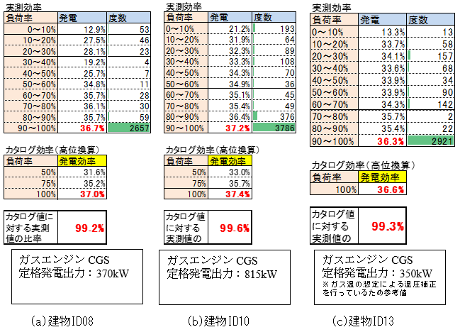
From 3 actual measurement data from the previous survey[3], a comparison between actual power generation efficiencies and catalog values (based on the performance test method that is prescribed in JIB 8122) was made, and as a result, Figure 4 was obtained. Based on this table, \(f_{ cgs, e, cor } = 0.99\) was set as a correction of power generation efficiency.
G.2 Heat loss rate of waste heat
| Constant name | Description | Unit | Value |
|---|---|---|---|
\(f_{ hr, loss }\) |
Heat loss rate of waste heat |
- |
0.97 |
Waste heat from a CGS is lost from the surface of its pipe during its operation, and the heat is lost because the temperature of circulating water in the pipe is lowered due to its intermittent operation. These losses of the heat were calculated based on the piping specifications of discharging hot water circuits that were obtained from two actual buildings.
The assumed piping specifications are shown in Table 48. The result of calculating the losses of waste heat from the surfaces of the pipes in the discharging hot water circuits of the two buildings based on the specifications shown in Table 48 is shown in Table 49. Where, the temperature of the circulating water is assumed to be 85℃, and the ambient temperatures of the pipes to be 15℃. Next, the result of calculating the heat loss caused by lowering of the in-pipe circulating water is shown in Table 50. On the assumption that the temperature of the circulating water is reduced from 85℃ to 15℃ after a CGS stops, waste heat that is lost due to the lowering of the temperature was assumed to be unavailable waste heat. Based on the unavailable waste heat, the losses of waste heat from the pipes were totalized and compared with the rated heat exhaust of the CGS. The comparison between the two is shown in Table 51. In this case, the operation time of the CGS was assumed to be 12 hours. As a result, the heat losses of 2.7% and 1.7% in Buildings A and B were expected, respectively. Accordingly, about 3% of obtained waste heat was considered to be lost, and a coefficient of the heat loss was set as \(f_{ hr, loss } = 0.97\).
| Building | Total of rated heat exhausts of CGS | Pipe length (pipe diameter) |
|---|---|---|
Building A |
38.4kW × 1 |
47.8m(25A) + 5.2m(32A) |
Building B |
52.5kW × 4 |
14.0m(50A) + 11.0m(80A) + 27.0m(100A) |
Building |
Pipe length |
Pipe diameter |
Assumed insulation thickness [4] |
Insulation specifications [5] |
Linear heat loss coefficient |
Temperature difference |
Heat loss |
Total of heat losses |
|---|---|---|---|---|---|---|---|---|
- |
m |
A |
mm |
- |
W/(m・K) |
K |
W |
W |
Building A |
47.8 |
25 |
20 |
Insulation specifications 2 |
0.270 |
70 |
903 |
1032 |
5.2 |
32 |
20 |
Insulation specifications 2 |
0.354 |
70 |
129 |
||
Building B |
14.0 |
50 |
20 |
Insulation specifications 3 |
0.388 |
70 |
380 |
2089 |
11.0 |
80 |
20 |
Insulation specifications 3 |
0.388 |
70 |
478 |
||
27.0 |
100 |
25 |
Insulation specifications 2 |
0.651 |
70 |
1230 |
Building |
Pipe length |
Pipe diameter |
Amount of holding water |
Temperature difference |
Heat loss amount |
Total of heat loss amounts |
|---|---|---|---|---|---|---|
- |
m |
A |
m3 |
K |
Wh |
Wh |
Building A |
47.8 |
25 |
0.0023 |
70 |
1904 |
2243 |
5.2 |
32 |
0.0040 |
70 |
339 |
||
Building B |
14.0 |
50 |
0.0270 |
70 |
2231 |
23928 |
11.0 |
80 |
0.0550 |
70 |
4487 |
||
27.0 |
100 |
0.0080 |
70 |
17210 |
Building |
Surface heat loss |
Assumed operation time |
Surface heat loss amount |
Heat loss amount due to intermittent operation |
Total of heat loss amounts |
Accumulated daily waste heat amount |
Heat loss ratio |
|---|---|---|---|---|---|---|---|
- |
W |
Hours |
kWh |
kWh |
kWh |
kWh |
% |
Building A |
1032 |
12 |
12.4 |
2.2 |
14.6 |
537.6 |
2.7 |
Building B |
2089 |
12 |
25.1 |
23.9 |
49.0 |
2940.0 |
1.7 |
G.3 CGS auxiliary module power ratio
| Constant name | Description | Unit | Value |
|---|---|---|---|
\(f_{ esub, cgswc }\) |
CGS’s auxiliary power ratio (in the presence of a cooling tower) |
- |
0.05 |
\(f_{ esub, cgsac }\) |
CGS’s auxiliary power ratio (in the absence of a cooling tower) |
- |
0.06 |
From one actual measurement datum from the previous survey[3], main module powers and power generation outputs during operation were averaged, and as a result, Table 53 was obtained. In CASCADEⅢ [6] used as reference for this program, an auxiliary power of a CGS is expected to be 5% of its power generation output, but actually was close to 6% of the output. In particular, the auxiliary powers of a cooling tower and and pump accounts for 1% of the output. In a large CGS with a cooling tower for heat dissipation, its auxiliary power is assumed to be larger, so in the case where a micro CGS (power generation output of 50kW or less) does not require a cooling tower because it has a radiator for heat dissipation, its auxiliary power ratio was traditionally set as \(f_{ esub, cgsac } = 0.05\), while an auxiliary power ratio of a larger CGS was set as \(f_{ esub, cgswc } = 0.06\).
Building ID01 |
CGS’s power generation output |
Auxiliary power |
|||||
|---|---|---|---|---|---|---|---|
CGS body |
Hot water circulating pump |
Cooling tower fan |
Cooling tower pump |
Total |
|||
Winter season |
Electric power |
700W |
17.4W |
11.1W |
0.4W |
3.3W |
32.2W |
Power generation output ratio |
- |
2.5% |
1.6% |
0.1% |
0.5% |
4.6% |
|
Intermediate season |
Electric power |
700W |
22.4W |
11.1W |
2.9W |
3.4W |
39.8W |
Power generation output ratio |
- |
3.2% |
1.6% |
0.4% |
0.5% |
5.7% |
|
Summer season |
Electric power |
700W |
22.6W |
11.0W |
4.2W |
3.3W |
41.1W |
Power generation output ratio |
- |
3.2% |
1.6% |
0.6% |
0.5% |
5.9% |
|
G.4 Maximum operation time of CGS in the case of intermittent operation.
| Constant name | Description | Unit | Value |
|---|---|---|---|
\(T_{ STn }\) |
Maximum operation time of CGS in the case of intermittent operation. |
h/day |
14 |
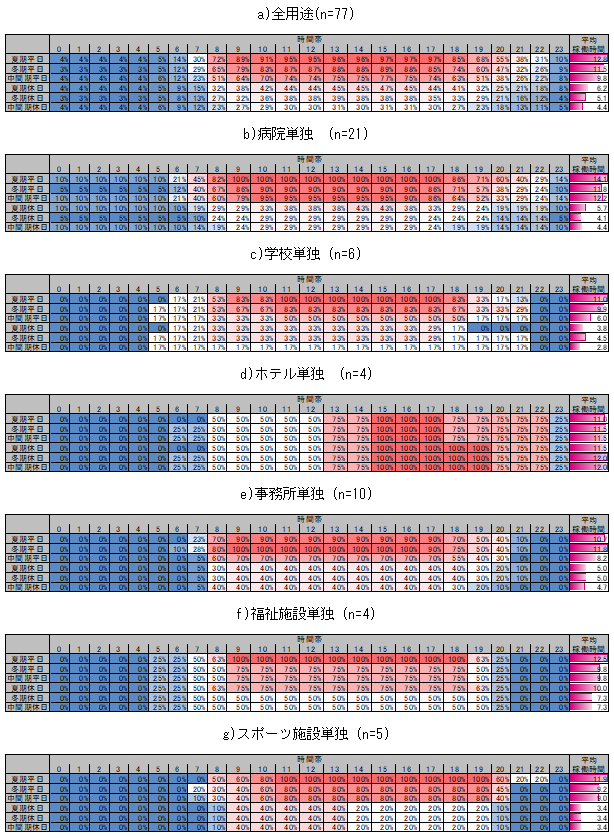
77 buildings with the introduction of a CGS responded to the questionnaire investigation of the previous survey[3]. The hourly availabilities of the CGS in these buildings were analyzed, and as a result, Table 55 was obtained. Table 55 shows the averaged hourly availability of the CGS in all uses and the total of its hourly availabilities in major uses. The availability of the CGS slightly depends on building uses, but the availability is high during 8:00 and 19:00 in a weekday of a summer season. In a hospital with the longest operation time of the CGS, the average operation time of the CGS in the weekday of during a summer season is about 14 hours. A trend in operation hours of the CGS in a hotel is greatly different from those in other uses, but the operation time of the GGS in the hotel is about 11 hours. The relevant operation time in the hotel is not so different from those in other uses.
The hearing survey for system designers that was separately conducted indicates the design concept that estimated hours based on the durable operation hours of the CGS (about 60000 hours but depending on each type of equipment) are 3000 to 4000, assuming that the durable period of the CGS is 15 years to 20 years. From the results of the questionnaire investigation and the hearing survey, assuming that the CGS does not operate on days with small loads such as holidays and days during the intermediate season, and judging that it is reasonable to assume that its maximum operation time per day is approximately 14 hours, the relevant time was set as \(T_{ STn } = 14\), regardless of building uses.
G.5 COP of absorption chiller/heater with auxiliary waste heat system recovery at use of waste heat
| Constant name | Description | Unit | Value |
|---|---|---|---|
\(f_{ COP, link, hr }\) |
COP at use of waste heat from absorption chiller/heater with auxiliary waste heat recovery |
- |
0.75 |
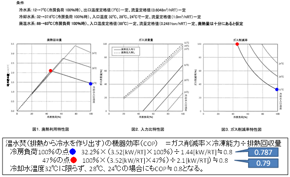
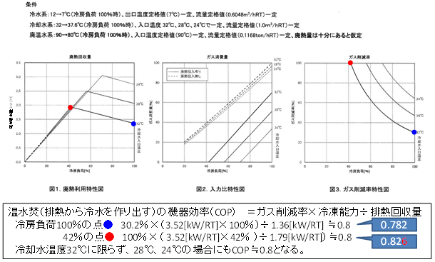
A manufacturer of absorption chillers/heaters with auxiliary waste heat system recovery provided data on the available waste heat amounts and gas consumptions of two models (Figure 5 and Figure 6). Based on the data, a COP (Coefficient Of Performance) the chiller/heater of the in the case where only waste heat is used to manufacture a cooling source was calculated and determined to be approximately 0.79 to 0.82. Accordingly, the relevant coefficient was set as \(f_{ COP, link, hr } = 0.75\).
G6. Required power ratio for operation judgment standard.and required heat ratio for operation judgment standard.
| Constant name | Description | Unit | Value |
|---|---|---|---|
\(f_{ eopeMn }\) |
Required power ratio for operation judgment standard |
- |
0.5 |
\(f_{ hopeMn }\) |
Required waste heat ratio for operation judgment standard |
- |
0.5 |
A required power ratio for operation judgment standard indicates how much power load is required to operate a CGS in comparison with a required heat ratio for operation judgment standard. The required heat ratio for operation judgment standard also indicates how much heat load is required to operate a CGS in comparison with a rated waste heat recovery. A judgment on whether to operate the CGS when the heat load is small depends on different buildings, and is often left up to site operation managers in the buildings For this reason, it is difficult to set a uniform load value that can be applied to every building, but a load factor of 50% is described in the performance test method for CGSs that is prescribed in JIB 8122. Some buildings where even in actual operation of the CGS, the CGS is operated at a partial load factor of about 50%, are observed. Accordingly, these ratios were set as \(f_{ eopeMn } = 0.5\) and \(f_{ eopeMn } = 0.5\).
G.7 Maximum share ratio of power load of CGS
| Constant name | Description | Unit | Value |
|---|---|---|---|
\(f_{ elmax }\) |
Maximum share rate of power load of CGS |
- |
0.95 |
Currently, power load control to cover all of power loads with generation of a CGS is not made. The common way of operating the CGS is to introduce power load control under which a part of electric power is always purchased to avoid a reverse power flow from occurring. In CASCADEⅢ [6], a default setting is to ensure 5% of an annual peak power as power to be purchased. In reference to this default setting, assuming that at least 5% of the power load is covered by purchasing electric power, the maximum share ratio was set as \(f_{ elmax } = 0.95\).
G.8 Available waste heat (rated condition) during rated operation of absorption chiller/heater with auxiliary waste heat system recovery and maximum load factor (rated condition) at possible operation of the chiller/heater with the use of only waste heat
| Constant name | Description | Unit | Value |
|---|---|---|---|
\(f_{ link, rated, b }\) |
Availability rate of waste heat of absorption chiller/heater with auxiliary waste heat system recovery during its rated operation |
- |
0.15 |
\(f_{ link, min, b }\) |
Maximum loading factor at which a waste heat of absorption chiller/heater with auxiliary waste heat system recovery can operate only by waste heat |
- |
0.3 |
The default values in CASCADEⅢ [6] were employed for these values.
G9. Rate of reduction of available waste heat by waste heat temperature
| Constant name | Description | Unit | Value |
|---|---|---|---|
\(f_{ link, down }\) |
Rate of reduction of available waste heat by waste heat temperature |
- |
0.125 |
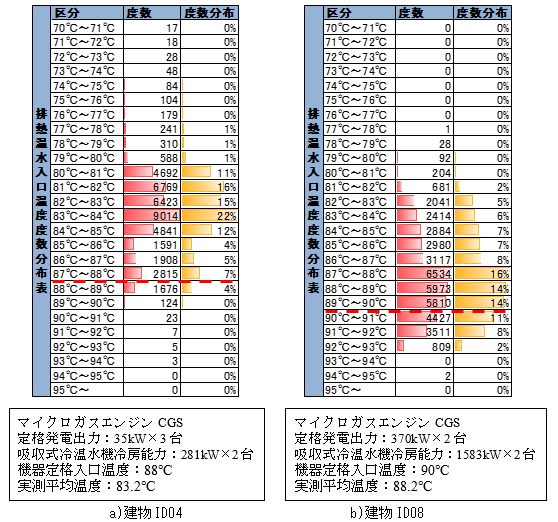
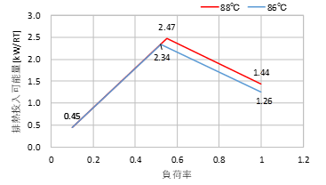
2 measured values in the previous survey [3] show a distribution of inlet temperatures of hot water that is discharged from an absorption chiller/heater with auxiliary waste heat system recovery, indicated in Figure 7. The two measured values show that the actual inlet temperatures of the absorption chillers/heaters with auxiliary waste heat system recovery are lower than their rated inlet temperature. In Building ID04, a first absorption chiller/heater with auxiliary waste heat system recovery is continuously connected to a second one, and discharged hot water after hot water is used in the first unit is charged into the second one. This is also considered to cause the inlet temperature of discharged hot water to be lower than the rated value of the equipment. Based on these results, the inlet temperature of hot water discharged from the absorption chiller/heater with auxiliary waste heat system recovery was considered to become approximately 2℃ lower that its rated value. Therefore, the characteristics of absorption chillers/heaters with auxiliary waste heat system recovery of two manufacturers were examined concerning their available waste heat amounts in the case where the temperatures of the discharged hot water in the chillers/heaters are reduced by 2℃. The characteristic of the equipment that was more affected by the reduction of the temperature is shown in Figure 8. As shown in the figure, when the temperature of the discharged hot water is reduced by 2℃, the available waste heat is reduced by 12.5% at a load factor of 1.0. Accordingly, the relevant reduction rate was set as \(f_{ link, down } = 0.125\).
G.10 Read of calculation results of other systems/ installations
G.10.1 Total of daily power consumptions (conversion to primary energy)
For the items of air conditioning equipment, mechanical ventilation equipment, lighting installations, hot-water supply systems. elevators, systems with effective use of energy (solar power system) and other, their total daily power consumptions are outputted as described below. These daily power consumptions are required to calculate a power load of a cogeneration system.
- Air conditioning equipment \(E_{ AC, total, d }\)
Output the following 4 total daily values [MWh/d].
- Power consumption of air conditioner group (MWh)\(E_{AC, ahu, i}\)
- Power consumption of secondary pump group (MWh) \(E_{ AC, pump, i }\)
- Power consumption of main module of heat source group (MWh) \(E_{ AC, ref, i }\)
- Power consumption of main module of heat source group (MWh) \(E_{ AC, ref, sub, i }\)
However, note the following requirements.
- The primary energy consumption of a main module of a heat source group, \(E_{AC, ref, i }\) (Formula 2.1.98/ [5] p191) shall be accumulated for only heat source equipment using electric power as an energy source, while that of heat source equipment using other energy sources shall not be accumulated.
- The power consumption of a main module of a heat source system group that is designated in Form 7-3 “⑪ Name of air conditioning heat source group (heating source) using waste heat” is not accumulated.
This is due to that the primary energy consumption of the main module of the heat source system that uses waste heat is reduced when a heat source load is covered by the waste heat, and so, the power load is overestimated if this consumption is estimated as a cogeneration power load.
- Mechanical ventilation equipment \(E_{ V, total, d }\)
The power consumption of mechanical ventilation equipment (MWh) \(E_{ v }\) (Formula 2.2.1/ [5] p283) is divided into each daily unit. The primary energy consumption that is equivalent to the total of daily consumption values is outputted.
- In the case where the equipment whose operation schedule is specified for a weekday or holidays, the power consumption is divided into each daily unit according to the relevant schedule. In the case where mechanical ventilation equipment whose annual operation hours is specified, the accumulated consumption value is divided by its operation days in a year. The result is a value of a one-day consumption.
- Lighting installation \(E_{ L, total, d }\)
The power consumption of a lighting installation (MWh) \(E_{ L }\) (Formula 2.3.1/[5] p295) is divided into each daily unit. The primary energy consumption that is equivalent to the total of daily consumption values is outputted.
- In the case where the equipment whose operation schedule is specified for a weekday or holidays, the power consumption is divided into each daily unit according to the relevant schedule. In the case where mechanical ventilation equipment whose annual operation hours is specified, the accumulated consumption value is divided by its operation days in a year. The result is a value of a one-day consumption.
- Hot-water supply system \(E_{ W, total, d }\)
The accumulated value of the power consumption of a hot-water supply system (targeted to only water heaters using electric power as an energy source)(MWh) \(E_{ w }\) (Formula 2.4.1/[5] p306) is divided into each daily unit. The primary energy consumption that is equivalent to the total of daily consumption values is outputted.
- When being divided into each daily unit, the energy consumption in a room with 365 annual days of hot-water supply is divided by 365. In the case where the annual days of hot-water supply is consistent with those under a room use pattern 1 in other room, the annual primary energy consumption of the hot-water supply system is divided by the annual days. The result is equivalent to a daily energy consumption under the room use pattern 1. Otherwise, an energy consumption obtained after an annual energy consumption of the hot-water supply system is divided by annual days of hot-water supply is equal to a daily energy consumption under the room use patterns 1 and 2.
- In the case where a fuel type of a water heater that is designated in Form 7-3 “⑫ Name of water heater using waste heat” is electric power, the primary energy consumption of this equipment is not accumulated.
This is due to that the primary energy consumption of a water heater in a system using waste heat is reduced when a hot-water supply load is covered by the waste heat, and so, the power load is overestimated if this consumption is estimated as a cogeneration power load.
- Elevator \(E_{ EV, total, d }\)
The power consumption of an elevator (MWh) \( E_{EV} \) (Formula 2.5.1/[5] p314) is divided into each daily unit. The primary energy consumption that is equivalent to the total of daily consumption values is outputted.
- When being divided into each daily unit, the daily power consumption is determined as calculated based on the annual operation hours of the elevator \(T_{ EV, i }\)([5] p316). The annual lighting hours under the standard use conditions in an elevator’s room use as “a room mainly providing service” are equal to the operation hours. That is to say, the power consumption of the elevator is divided into a daily unit in the same way when the primary energy for lighting is divided into a daily unit in the “room mainly providing service.”
- Systems with effective use of energy (solar power generation) \(E_{ PV, total, d }\)
The accumulated daily value of a solar power system’s self-consumption of its generation \(E_{ PV\_consumption }\)(Formula 2.6.5・Formula 2.6.6/ [5] p327) is outputted.
- Other \(E_{ M, total, d }\)
Other power consumption (MWh) \( E_{M} \) (Formula 3.6.1/[5] p402) is divided into each daily unit. The primary energy consumption that is equivalent to the total of daily consumption values is outputted. The power consumption is divided into each daily unit according to equipment’s heating schedule for each room use.
G.10.2 Accumulated daily primary energy consumption (cool source group) of main module of absorption chiller/heater with auxiliary waste heat system recovery (absorption chiller/heater)(single and double combination) \(E_{ AC, ref, c, d }\)
The accumulated daily primary energy consumptions of the main modules of the following heat source models that are included in Form 7-3 “⑩ Name of air conditioning heat source group (cooling source) using waste heat, \(E_{ AC, ref, i }\) (Formula 2.1.98/ [5] p191), are outputted only in a period for operation of the main modules as a cool source system.
In the case where a heat storaging tank is included in “air conditioning heat source using waste heat, however, the accumulated daily primary energy consumption of the heat source group for additional operation is outputted in the same way mentioned above.
Model |
XML |
|---|---|
Absorption chiller (steam) |
AbcorptionChiller_Steam |
Absorption chiller (cooling water changing discharge, steam) |
AbcorptionChiller_Steam_CTVWV |
Absorption chiller (hot water) |
AbcorptionChiller_HotWater |
Absorption chiller (single and double combination, city gas) |
AbcorptionChiller_Combination_CityGas |
Absorption chiller (single and double combination, cooling water changing discharge, city gas) |
AbcorptionChiller_Combination_CityGas_CTVWV |
Absorption chiller (single and double combination, LPG) |
AbcorptionChiller_Combination_LPG |
Absorption chiller (single and double combination, cooling water changing discharge, LPG) |
AbcorptionChiller_Combination_LPG_CTVWV |
Absorption chiller (single and double combination, steam) |
AbcorptionChiller_Combination_Steam |
Absorption chiller (single and double combination, cooling water changing discharge, steam) |
AbcorptionChiller_Combination_Steam_CTVWV |
G.10.3 Representative load factor of cool source group with absorption chiller/heater with auxiliary waste heat system recovery (absorption chiller/heater (single and double combination)), \(mxL_{ AC, ref, c, d}\)
The representative load factor in Form 7-3 “⑩ Name of air conditioning heat source group (cooling source) using waste heat,” \(mxL_{ AC, ref, i(m,n) }\) (Formula 2.1.91・Formula 2.1.93/ [5] p189), is outputted by day.
In the case where a heat storaging tank is included in “air conditioning heat source using waste heat, however, the accumulated daily primary energy consumption of the heat source group for additional operation is outputted in the same way mentioned above.
G.10.4 Accumulated daily primary energy consumption of main module of heat source group using waste heat, \(E_{ AC, ref, h, hr, d }\)
The accumulated daily primary energy consumption of the main module of a heat source group that is included in Form 7-3 “⑪ Name of air conditioning heat source group (heating source) using waste heat, \(E_{ AC, ref, i }\) (Formula 2.1.98/ [5] p191), are outputted only in a period for operation of the main module as a cool source system.
- The primary energy consumptions of all pieces of heat source equipment in the subject heat source group, regardless of which fuel type is used, are accumulated.
In the case where a heat storaging tank is included in “air conditioning heat source using waste heat, however, the accumulated daily primary energy consumption of the heat source group for additional operation is outputted in the same way mentioned above.
G.10.5 Heat source load of heat source group using waste heat, \(q_{ AC, ref, h, hr, d }\)
The heat source load of a heat source group in Form 7-3 “⑪ Name of air conditioning heat source group (heating source) using waste heat, \(Q_{AC, ref, i, d }\) (Formula 2.1.86/ [5] p184), is outputted by day.
In the case where a heat storaging tank is included in “air conditioning heat source using waste heat, however, the accumulated daily primary energy consumption of the heat source group for additional operation is outputted in the same way mentioned above.
G.10.6 Primary energy consumption of hot-water supply system using waste heat, \(E_{ W, hr, d }\)
The annual primary energy consumption of a hot-water supply system of a water heater in Form 7-3 “⑫ Name of water heater using waste heat,” \(E_{ w }\) (Formula 2.4.1/ [5] p306), is divided by day. Each value after being divided is outputted.
- The way of dividing the consumption each daily unit is the same as in the item of hot-water supply described in “ ① Accumulated daily power consumption (primary).”
G.10.7 Hot-water supply load of hot-water supply system in system available to waste heat, \(q_{ W, hr, d }\)
The annual hot-water supply load of a water heater in Form 7-3 “⑫ Name of water heater using waste heat,” \(Q_{ wr, i }\) (Formula 2.4.2/ [5] p306), is outputted by day.
G.10.8 Accumulated daily operation time of air conditioning (cool source group), \(T_{ AC, c, d }\)
There is an air conditioner group in Form 7-3 “⑩ Name of air conditioning heat source group (cool source)” that is designated as the name of a cool heat source in Form 2-7 (Air conditioning) air conditioner input sheet. The cooling operation time of the air conditioner group, \(T_{ AC, ahu, c, i, d }\) (Formula 2.1.57~61/ [5] p173), is outputted by day.
In the case where a heat storaging tank is included in “air conditioning heat source using waste heat, however, the accumulated daily primary energy consumption of the heat source group for additional operation is outputted in the same way mentioned above.
G.10.9 Accumulated daily operation time of air conditioning (heat source group), \(T_{ AC, h, d }\)
There is an air conditioner group in Form 7-3 “⑩ Name of air conditioning heat source group (heat source)” that is designated as the name of a cool heat source in Form 2-7 (Air conditioning) air conditioner input sheet. The heating operation time of the air conditioner group, \(T_{ AC, ahu, c, i, d }\) (Formula 2.1.62~64/p174), is outputted by day.
In the case where a heat storaging tank is included in “air conditioning heat source using waste heat, however, the accumulated daily primary energy consumption of the heat source group for additional operation is outputted in the same way mentioned above.
G.11 Way of calculating coefficient (difference in average power between operation and non-operation hours of building)
1) Obtain schedules for ① air conditioning operation, ② lighting heat generation and ③ equipment heat generation in room uses of a building to be calculated (matrix of 8760×1).
*Database to be used ROOM_COND.csv
*The schedule for air conditioning operation (including decimals) that is larger than 0 or is o, is deemed to be “1” or to be “0,” respectively. Other schedules are allowed to have decimals.
2) Calculate a schedule for weighing floor areas at the following time t in room uses of a building to be calculated (matrix of 8760×1).
“Room where air conditioning is calculated,“ described in Form 1
Room where lighting is calculated,“ described in Form 1
All rooms described in Form 1
1) Using the above schedule at each time that was determined in the above section, calculate a ratio when an accumulated value at each day is 1(matrix of 8760×1).
Where,
\( Sawdsum_{ac}(d) \): Accumulated value of \( Sawt_{ac}(t) \) on date \( d \) (accumulated from 1:00 to 24:00 each day)
\( Sawdsum_{lt}(d) \): Accumulated value of \( Sawt_{lt}(t) \) on date \( d \) (accumulated from 1:00 to 24:00 each day)
\( Sawdsum_{oa}(d) \): Accumulated value of \( Sawt_{oa}(t) \) on date \( d \) (accumulated from 1:00 to 24:00 each day)
4) Calculate a power consumption at a time t on a date d in the whole building to be calculated (matrix of 8760×1).
Where,
\( Eac_{ele}(d) \): Accumulated daily power consumption of air-conditioning equipment on date \( d \) [MWh/day]
\( Ev_{ele}(d) \): Accumulated daily power consumption of mechanical ventilation equipment on date \( d \) [MWh/day]
\( Elt_{ele}(d) \): Accumulated daily power consumption of lighting installation on date \( d \) [MWh/day]
\( Ehw_{ele}(d) \): Accumulated daily power consumption of the hot-water supply system on date \( d \) [MWh/day]
\( Eev_{ele}(d) \): Accumulated daily power consumption of the elevator on date \( d \) [MWh/day]
\( Eoa_{ele}(d) \): Accumulated daily power consumption of other equipment on date \( d \) [MWh/day]
5) Calculate a coefficient at a date \( d \), \( f_{eopeHi}(d) \).
Where,
\( Epv_{ele}(d) \) is the accumulated daily power generation of the solar power system on date \( d \) [MWh/day].
A range of the coefficient is as shown above.